I. Drawing the mold diagram
Before drawing the assembly drawing of the mold, it is necessary to draw the process diagram and meet the requirements of the part drawing and process data. The dimensions guaranteed by the next process should be marked with the words “process dimensions” on the drawing. If no further mechanical processing is performed after forming except for deburring, then the process diagram is exactly the same as the part drawing.
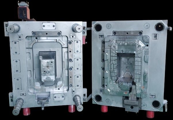
It is best to indicate the part number, name, material, material shrinkage rate, drawing scale, etc. under the process diagram. Usually, the process diagram is drawn on the mold assembly drawing.
When drawing the assembly drawing, try to use a scale of 1:1. Start by drawing the cavity first, and draw the front view simultaneously with the other views.
The general assembly drawing of the mold should include the following contents:
Structure of the molding part of the mold:
The structural form of the pouring system and exhaust system.
The parting surface and the way of parting the mold.
The overall structure and all the connections, the positioning and guiding of the components.
Mark the height dimension of the cavity (not required, depending on needs) and the overall size of the mold.
Auxiliary tools (part removal and mold release tools, correction tools, etc.).
Assign sequential numbers to all parts and complete the parts list.
Mark technical requirements and instructions.
Technical requirements for the general assembly drawing of the mold:
The performance requirements for certain systems of the mold, such as the assembly requirements for the ejection system and the slider core-pulling structure.
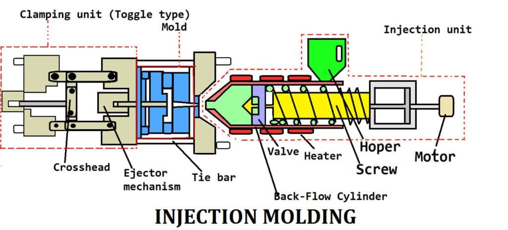
Requirements for mold assembly processes. For example, the fit clearance between the parting surfaces of the mold after assembly should not exceed 0.05mm. The parallelism requirements for the upper and lower surfaces of the mold should be specified, and the dimensions determined by assembly and the requirements for these dimensions should be indicated.
Mold use and assembly/disassembly methods.
Requirements for oxidation resistance treatment, mold numbering, lettering, marking, oil seal, storage, etc.
Requirements for mold testing and inspection.
The order of drawing part drawings from the mold assembly drawing should be: inside first, outside second, complex first, simple second, molded parts first, structural parts second.
The requirements are as follows:
Graphic requirements
It is necessary to draw according to scale, allowing for enlargement or reduction. The view selection is reasonable, the projection is correct, and the layout is appropriate. In order to make the processing patent number easy to understand and facilitate assembly, the graphics should be as consistent as possible with the general assembly drawing, and the graphics should be clear.
The requirements for dimensioning are unified, centralized, orderly, and complete
The order of dimensioning is: first mark the dimensions of the main parts and the molding slope, then mark the fit dimensions, and then mark all dimensions. On non-main part drawings, mark the fit dimensions first, and then mark all dimensions.
Surface roughness
The most commonly used roughness is marked on the upper right corner of the drawing, such as “the rest is 3.2.” Other roughness symbols are marked on each surface of the part.
Other content
For example, the part name, mold drawing number, material grade, heat treatment and hardness requirements, surface treatment, graphic scale, processing accuracy of free dimensions, technical specifications, etc. must be filled in correctly.
II. Proofreading and drawing review
The relationship between the mold and its parts and the plastic part drawings
Whether the material, hardness, dimensional accuracy, and structure of the mold and mold parts meet the requirements of the plastic part drawings.
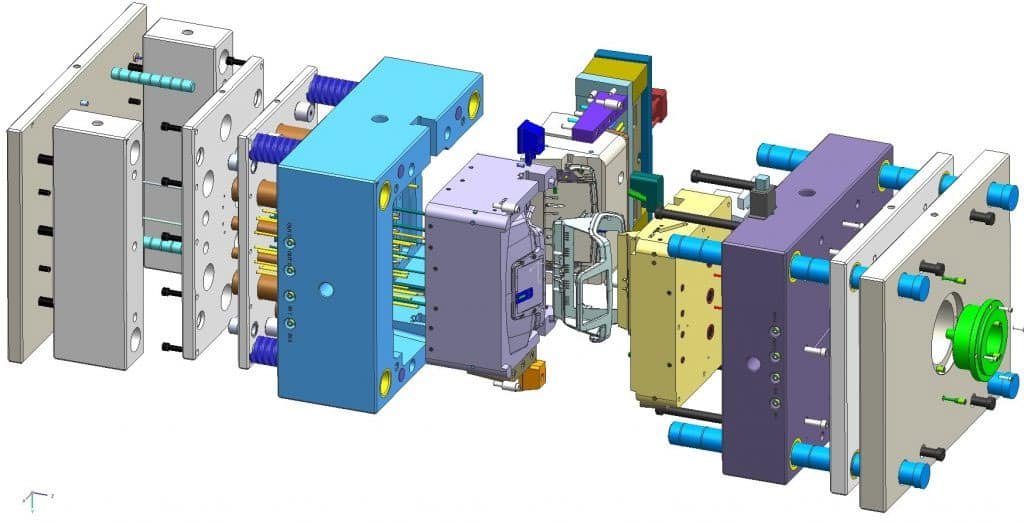
Plastic parts
Whether the flow of plastic material flow, shrinkage cavity, weld mark, crack, demolding slope, etc. affect the requirements of plastic parts in terms of performance, dimensional accuracy, surface quality, etc. Whether there are deficiencies in pattern design, whether processing is simple, and whether the shrinkage rate of molding materials is selected correctly.
Forming equipment
Whether the injection volume, injection pressure, clamping force are sufficient, the installation of the mold, the core of the plastic part, and the demolding are problem-free, and the nozzle and mouthpiece of the injection machine are properly contacted.
Mold structure
Whether the position of the parting surface and the finishing accuracy meet the requirements, whether there will be overspill, and whether the plastic parts can be ensured to remain on the side of the mold with an ejection device after mold opening.
Whether the demolding method is correct, the size, position, and quantity of the push rod and push tube are appropriate, and whether the push plate will be stuck by the core and cause scratching of the molded part.
Mold temperature adjustment. The power and quantity of heaters; the location, size, and quantity of cooling medium flow lines are appropriate.
The method for processing the undercuts of plastic parts, and whether the mechanism for removing the undercuts is appropriate, such as whether the slider and push rod in the bevel guide core-pulling mechanism interfere with each other.
Whether the position and size of the pouring and exhaust system are appropriate.
Design drawings
Whether the placement positions of each mold part on the assembly drawing are appropriate, whether the representation is clear, and whether there are any omissions;
The part number, name, production quantity, internal or external production of the part, standard or non-standard part, processing accuracy of the part, correction and processing of high-precision dimensions of the molded plastic part, and the material, heat treatment, surface treatment, and surface finishing degree of the mold parts are clearly marked and described on the part drawing.
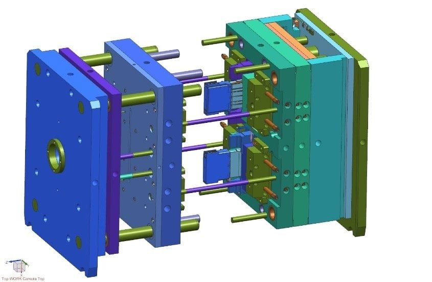
The working dimensions and fit dimensions of the main parts and molded parts of the parts. The dimensions should be correct and not require the producer to make conversions.
Check the view position of all part drawings and assembly drawings, whether the projection is correct, whether the drawing method complies with the national standard for drawing, and whether there are any missing dimensions.
Check the processing performance
Whether the geometric structure, drawing method, and dimensioning of all parts are conducive to processing
The main working dimensions of the recalculation auxiliary tool:
In principle, professional proofreading should be conducted according to the designer’s self-proofreading project; however, it should focus on structural principles, process performance, and operational safety. When drawing, it is necessary to first digest the graphics, depict them according to international standards, and fill in all dimensions and technical requirements. After drawing, self-proofread and sign.
The traced base map is submitted to the designer for review and signature. It is customary for the relevant technical personnel from the tool manufacturing unit to review, countersign, and inspect the manufacturing process before it can be sent for exposure.
Write manufacturing process cards
The technician of the tool manufacturing unit shall prepare the manufacturing process card and make preparations for the processing and manufacturing.
In the manufacturing process of mold parts, inspection should be strengthened, with the focus on dimensional accuracy. After the mold assembly is completed, the inspector conducts inspection according to the mold inspection form, mainly to check whether the performance of the mold parts is good. Only in this way can the manufacturing quality of the mold be guaranteed.
III. Trial mold and mold repair
Although mold design is carried out under the expected process conditions when selecting the molding material and molding equipment, people’s understanding is often incomplete. Therefore, it is necessary to conduct a mold test after the mold processing is completed to see how the molded part quality is. After discovering the problem, it is necessary to correct the error and repair the mold.
There are many types of undesirable phenomena in plastic parts, and the causes are also complex. There are reasons related to the mold as well as the process conditions, and the two are often intertwined.
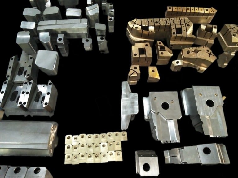
Before repairing the mold, a detailed analysis should be conducted based on the actual situation of the defects occurring in the plastic parts. The cause of the defects should be identified and remedial measures should be proposed. Because the molding conditions are easily changed, it is generally recommended to first change the molding conditions. If the changes cannot solve the problem, then repairing the mold should be considered.
Repairing molds should be more cautious, and it is not advisable to act rashly without full confidence. The reason is that once the mold conditions are changed, it is impossible to make major modifications and restore the original state.
Whether the performance of the parts is good is the only way to ensure the quality of the mold manufacturing.
IV. Sorting out data for archiving
After testing, if the mold is not to be used for a while, it should be completely wiped clean of mold release residue, dust, oil, and other contaminants, coated with butter or other anti-rust oil or rust preventatives, and stored in a safe place.
From the beginning of designing the mold to the successful completion of mold processing and inspection, the technical data generated during this period, such as task specifications, part drawings, technical specifications, mold assembly drawings, mold part drawings, base drawings, mold design specifications, inspection records, and mold repair records, should be systematically organized, bound, numbered, and filed according to regulations. This may seem cumbersome, but it is very useful for repairing molds and designing new molds in the future.
