The plastic part of the cable connector is an important component of the automotive wiring harness system and is a key assembly part. Due to the need for assembly and fixing of internal parts of the equipment, the top surface of the plastic part is designed with two screw holes for clamping structure, and the two ends of the plastic part are designed with four buckle structures, which increases the difficulty of molding. In this example, by setting up different types of slider core-pulling mechanisms, the problem of molding and demolding of the plastic part is solved.
01. Analysis of the structural process of plastic parts
The plastic material of the automotive cable connector shown in Figure 1 is PA66+GF30 (brand: Japan Toray CM3001G-30), with a density of 1.37g/cm3, a shrinkage rate of 0.4% to 0.8%, a mold forming temperature range of 80 to 100℃, and a melt temperature range of 260 to 310℃. It has excellent wear resistance, flame retardancy, self-lubricity, high mechanical strength, but high water absorption, resulting in poor standard stability. It is widely used in the manufacture of mechanical, automotive, chemical and electrical equipment parts, and is a widely used thermoplastic engineering plastic.
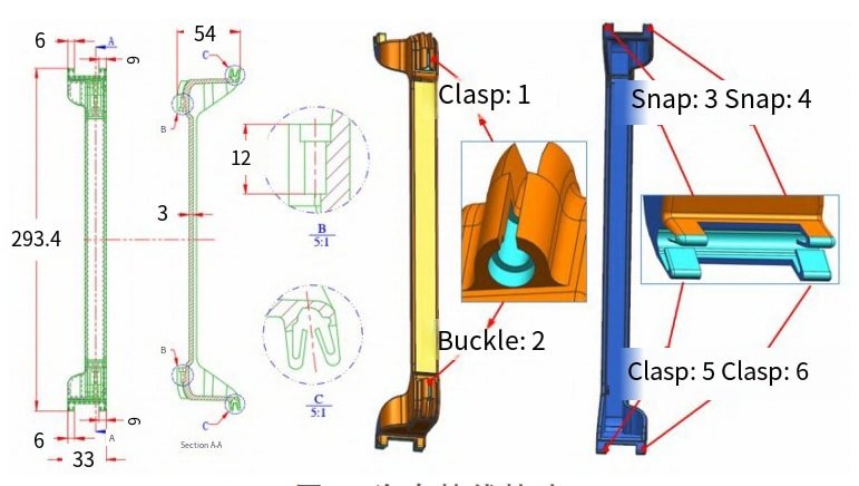
The overall dimensions of the plastic part are 293.4mm×33mm×54mm, with an average wall thickness of 3.0mm and a maximum thickness of 5.6mm at the screw clamping point. After molding, the plastic part is required to have a bright surface, no burrs, no damage to the buckle, and a clamping force that meets the predetermined target value. Considering the structural stability of mass production and reducing mold costs, the buckles 1 and 2 in Figure 1 will be molded using a spring-loaded front mold slider due to their location on the front mold side; buckles 3-6 will be molded using a conventional rear mold slider core-pulling method.
02. Key points of mold design
Design of the Pouring System
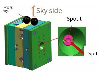
Since the layout of the cavity is closely related to the layout of the gating system, the mold is designed as the first mock examination with two cavities, taking into account the production batch, overall dimensions, injection capacity of the injection molding machine and other factors. Taking into account the need for a core pulling structure on the top surface of the plastic part, mass production, and the specific structure and layout of the mold, a pouring system with a cold runner and a large water gate side gate, as shown in Figure 2, was designed with one point injection of glue (one product per point). The diameter of the main channel inlet is 3mm; The diversion channel adopts a regular circular cross-section channel with a diameter of 8mm and a gate end face size of 10mm x 1.0mm. When opening the mold, the pouring system aggregates move with the product, and then secondary trimming is performed to remove the sprue.

Design of Moulded Parts
The molded parts mainly include the front mold core, the rear mold core, the slider, and the ejector pin. This mold is designed in a split-type design, where the front mold core and the rear mold core are inlaid and assembled, forming the main body of the molded plastic parts; the slider forms the buckle part; and the ejector pin is only used for ejection and exhaust. The mold design module of UG12 is used for split-type design, and the final detailed drawings of the split-type, front and rear mold cores are shown in Figure 3.
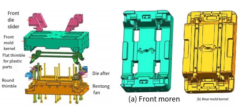
Based on the material, production batch, use and surface requirements for plastic parts, both front and rear mold cores are made of German Buderus hot work tool steel 1.2344 with factory hardness of 229HB. Electroslag remelted steel is known for its uniform material, excellent hardenability, good mechanical processing performance and polishing results, as well as high toughness and plasticity with superior high temperature wear resistance, fatigue resistance and heat resistance characteristics. After heat treatment and quenching, the hardness reaches 52-56HRC. The slider is composed of German Gritz H13 hot work tool steel which boasts excellent hardenability, low deformation rate during heat treatment, good toughness, wear resistance, cutting performance and thermal crack resistance properties. Thimbles are constructed using SKD61 hot work tool steel, which boasts high strength, good cutting performance, toughness and wear resistance – qualities that help ensure its long term wear resistance and thermal crack resistance. When chosen correctly this material can ensure the wear resistance and thermal crack resistance of sliders. By choosing this material thimbles can have superior strength, toughness and wear resistance properties.
Overall layout and structural design
In view of the shape and structure of the automotive cable connector, a simplified three-plate cold runner horizontal mold structure is adopted, and the overall structure of the designed mold is shown in Figure 4.
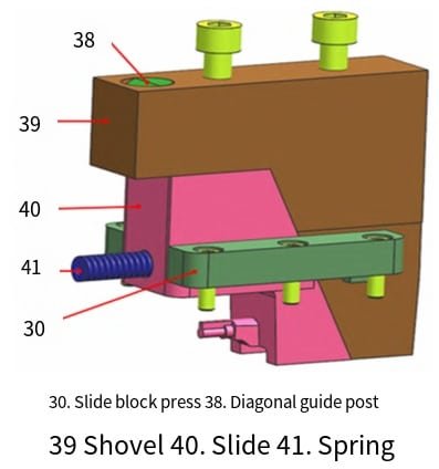
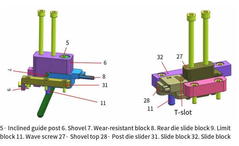
The front mold slide core-pulling structure mainly consists of a slide block, a slanted guide post, a shovel, a slide, and a spring, as shown in Figure 5. The slide block is fixed to the front mold core, the slanted guide post is fixed to the shovel, the shovel is fixed to the upper fixed plate, and the slide is restricted to move between the slide block and the front mold core. The spring is restricted between the slide and the front mold core.
The core-pulling structure of the rear mold slide (due to the similar structure of several rear mold slides, only one of them is discussed here) mainly consists of a bevel guide post, a shovel, a wear-resistant block, a rear mold slide, a limit block, a wave screw, and a slide pressure block, as shown in Figure 6. The bevel guide post is fixed in the shovel, which is fixed on the A plate, and the wear-resistant block is fixed on the rear mold slide. The rear mold slide is restricted to move between the slide pressure block, limit block, wave screw, rear mold core, and B plate. The limit block and wave screw are both fixed on the B plate, and the slide pressure block is fixed on the rear mold core and B plate.
Other system design
1. Design of guidance and positioning system
Due to the irregular shape of the automotive cable connector, the high mold structure is complex. In order to ensure the assembly tolerance requirements of the product and ensure accurate mold clamping and convenient maintenance after long-term use of the mold, this mold has designed a guiding and positioning combination system consisting of guide posts, guide sleeves, and 5° finger gaps on the mold core, as shown in Figure 7. This system can achieve rapid and precise guidance during mold operation, and can also prevent dislocation caused by mold wear after long-term production.

2. Design of exhaust system
The mold uses the clearance between the parting surface, the ejector pin hole, the slider and the mold core, and the clearance between the sliders to exhaust air.
3. Cooling system design
To ensure that the mold temperature remains within the specified temperature range during production, the mold uses a circulating cooling water circuit on the A plate, front mold core, rear mold core, and B plate. The mold cooling system ensures uniform cooling throughout the cavity, short molding cycle, and high surface quality of the plastic parts.
03.Mold working process
When using the mold, first remove the lock module, and then connect the mold cooling system to the external cooling source
(1) During mold opening, under the mold opening force of the mold injection machine and the elastic force of the spring 33, the upper fixed plate 1 separates from the A plate 2 in Figure 8 (note: the A plate 2 and the B plate 14 are connected together due to the action of the nylon rubber plug 35).
The upper fixed plate 1 drives the shovel 39 to separate from the front mold slider 40. At this time, the front mold slider 40 moves backward along the slider pressing block 30 under the force of the inclined guide post 38 and the elastic force of the spring 41 to perform core pulling. The predetermined core pulling distance is completed under the limit of the limit screw 34. Continue to open the mold, and under the force of the mold opening force of the injection machine, the nylon rubber plug 35 temporarily loses its adhesive force, and the A plate 2 and the B plate 14 begin to separate.
The shovel 6 and 27 also separate from the rear mold slider 8 and 28 along with the A plate 2, and the inclined guide post 5 fixed on the shovel 6 moves backward along the slider pressing block 31 until the predetermined core pulling distance is completed under the limits of the wave screw 11 and the limit block 9. The core pulling is completed (at the same time, the rear mold slider 28 also completes the core pulling action under the action of the T-slot on the shovel 27 and the limit of the wave screw 11). Continue to open the mold until it reaches the predetermined position set by the injection machine. Then, the top bar of the injection machine moves upward against the lower ejector plate 19, and the flat ejector pin 17 and round ejector pin 29 fixed on the ejector plate 18 and 19 push the plastic part 26 upward.
The spring 43 wrapped around the return pin 42 compresses upward under the ejecting force. Continue to eject until it reaches the limit block 44, and then remove the plastic part 26.
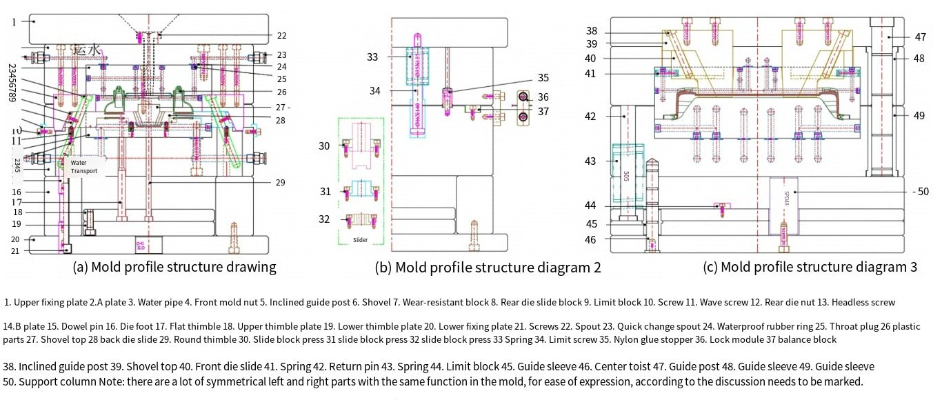
(2) During mold clamping. In the open mold state, the top rod on the injection molding machine is retracted, and the spring 43 in the compressed state is released to rebound, causing the ejector pins 18 and 19 to return and drive the flat ejector pin 17, round ejector pin 29, and return pin 42, which are fixed on them, to return.
Under the mold clamping force of the injection molding machine, the rear mold part moves back, and the rear mold slider 8 starts to compress the wave screw 11 under the force of the inclined guide post 5 to return (at the same time, the rear mold slider 28 also starts to compress the wave screw 11 under the force of the T-slot on the shovel 27 to return); continue to mold clamping until the spring 43 is released to return, and the balance block 37 on the B plate 14 starts to contact and close with the end face of the A plate 2 (at the same time, the rear mold core 12 starts to contact and close with the parting surface of the front mold core 4), until the parting surface is closed (the rear mold sliders 8 and 28 also return to their positions at the same time).
Continue to mold clamping, and the spring 33 in the released state starts to compress. The front mold slider 40 starts to compress the spring 41 under the force of the inclined guide post 38 to return; continue to mold clamping until the compressed spring 33 returns, and the A plate 2 and the end face of the upper fixed plate 1 are completely closed (the nylon plug 35 and the front mold slider 40 also return to their positions at the same time).
Conclusion:
Through the analysis of the plastic structure of the automotive cable connector, under the specific circumstances of considering the gate position, mass production, and mold layout requirements, a pouring system plan was developed using a cold runner large gate side gate with one point of injection (one product with one point). When designing the mold using UG and CAD, the selection of the mold parting surface, the structure of the cavity and core, the guiding and positioning mechanism, lateral parting and ejection, reset mechanism, cooling system, exhaust system, etc. were completed. The characteristics, key points, and difficulties of the automotive cable connector injection mold were elaborated in detail. In this process, a guiding and positioning combination system consisting of guide posts, guide sleeves, and mold core original 5° tiger mouths was used. A spring plate front mold slider was used, and a diagonal guide post or T-slot shovel was used to drive the rear mold slider to complete lateral core pulling. The injection mold structure using a flat ejector pin and a round ejector pin combination ejection mechanism was also used to improve the quality of the plastic part molding.
This case has strong practicality, solving the limitation of multiple buckles in different positions within the product and improving the design imagination of the product. It not only reduces the defective rate during mass production, but also saves mold costs. The mold has been tested in production practice, and the mold structure is simple and reasonable, producing plastic parts that meet design requirements.