1. Definition

Hot runner mold is an injection mold designed for thermoplastic materials, which uses heating or insulation methods to keep the plastic in the runner in a molten state, thereby achieving the goal of no or less runner solidification. It is also known as a runner free mold.
2. Comparison of advantages and disadvantages
2.1 Advantages: There are many advantages of hot runner molds, mainly manifested as:
2.1.1 Without or with very little channel condensate, the effective utilization rate of plastic is high, and the plasticizing ability of the injection machine can be fully utilized.
2.1.2 The pressure loss of molten plastic in the flow channel is small, making it easy to fill the mold cavity and supplement it, which can effectively avoid the occurrence of plastic depression, shrinkage cavity, and deformation.
2.1.3 Shortened the molding cycle and improved production efficiency.
2.1.4 The gate can be automatically cut, improving the level of automation.
2.1.5 can reduce injection pressure and lock mold tonnage.
2.2 Disadvantages:
Hot runner molds also have their corresponding disadvantages, mainly manifested as:
2.2.1 Molds equipped with hot runner plates have an increased closing height, which may require the use of larger injection machines.
2.2.2 The heat in the hot nozzle and hot runner plate affects the temperature of the front mold through thermal radiation and conduction. When designing the mold, efforts should be made to minimize heat transfer and strengthen the front mold
Cooling. The cost of molds is relatively high.
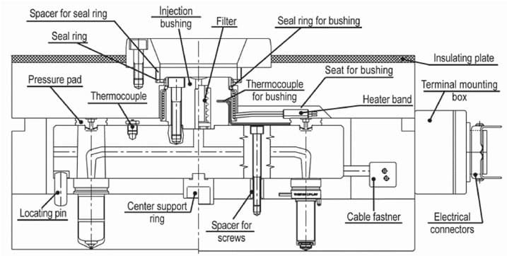
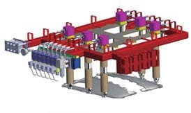
The basic structure of hot runner molds:
3. Classification of hot mouthpieces:
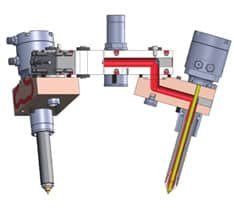
3.1 Hot nozzles can be roughly divided into two categories. Some common models of “HUSKY” hot nozzles, as shown in the following figures.
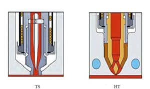

3.2 Characteristics of each heat pump nozzle:
3.2.1 The open hot nozzle TS is particularly suitable for hot to cold or sub channel applications. It can reduce the residue at the injection port. As shown in the following figure:
3.2.2 Hot spot nozzle HT
Especially suitable for applications with amorphous resins, larger particle resins, and wear resistance.
3.2.3 Valve needle nozzle VG, VX
VG: Suitable for applications that do not require injection residue. Especially suitable for amorphous and semi crystalline resins.
VX: Used for high temperature and wear resistance applications that require VG quality injection ports. As shown in Figure 5

4. Notes on hot runner mold design

4.1 Injection amount
Suitable hot nozzles should be selected based on the volume size of the rubber parts and different rubber materials. We mainly use two types of hot nozzle specifications and models: U500/U750.
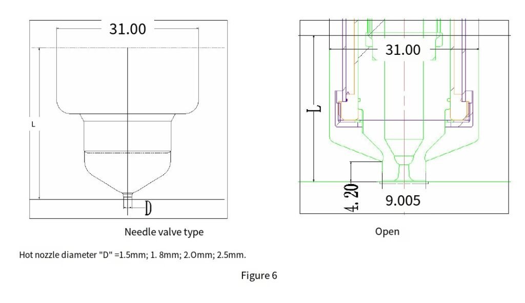
1) U750 specification (widely used in large phone case products). L=The number from the top of the hot nozzle to the bottom of the mold, rounded as an integer as much as possible.
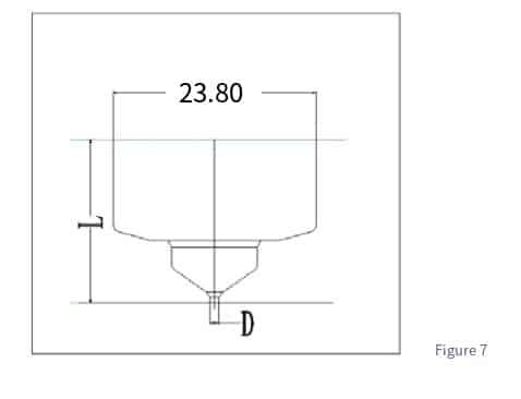
2) U500 specifications
The commonly used parameter is shown in Figure 7 on the right, where the diameter of the hot nozzle is “D”=1.0mm; 1.5mm.
4.2 Temperature control
The temperature of the hot nozzle and hot runner plate is directly related to the normal operation of the mold, so when designing the waterway, attention should be paid to strengthening the cooling near the hot nozzle.
4.3 Try to use standard hot nozzle specifications as much as possible
When ordering dual nozzle and multi nozzle hot runner models, we should try to use standard nozzle sizes as much as possible. Because non-standard models are many times higher than the standard in terms of price and delivery time.
4.4 The allowed gate forms for rubber parts;
Is it allowed for the top of the hot nozzle to participate in the molding of the adhesive part? Are there any requirements for the shape and appearance of the adhesive mouth? Is it needle point injection or other types of injection?
4.5 Hot mouthed mouth length;
The determination of the nozzle length for the hot nozzle and hot runner molds is different, as shown in the attached figure. In order to better understand the design of hot runner molds, the following are two most commonly used hot runner structural forms and methods for determining nozzle length.
Note: Calculation of length when ordering hot runner: (During design, the mouth length should be rounded as much as possible)
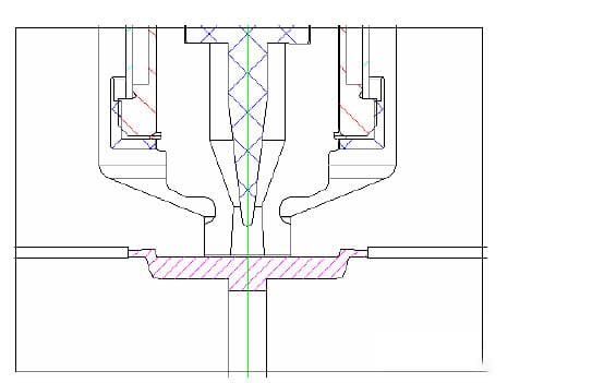
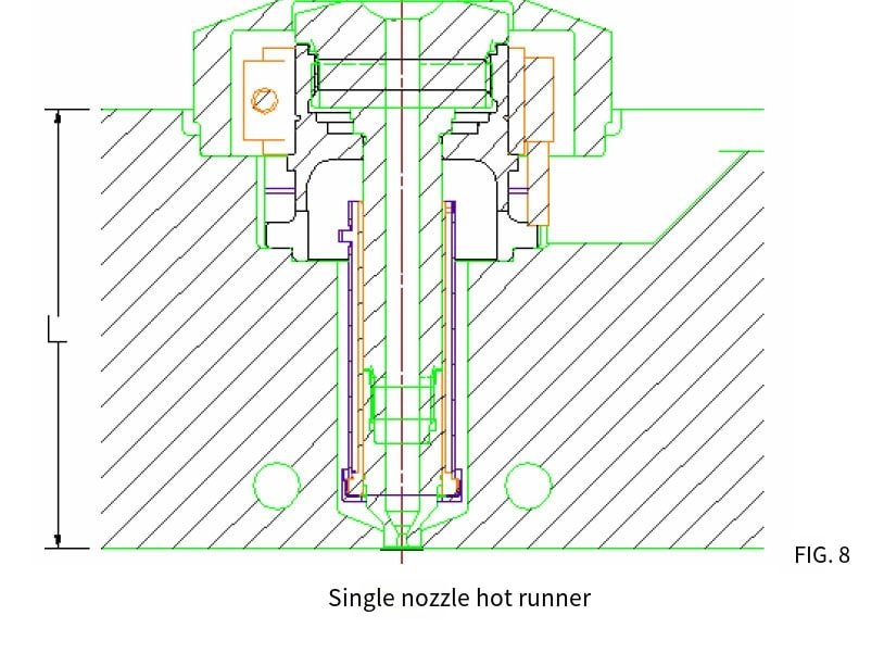
1) Single nozzle hot runner:
The distance from the surface of the hot nozzle on the mother mold to the top surface of the upper fixed plate (as shown in the figure below)
“L”=ordering mouth length; The length of a single hot runner is generally taken as a multiple of “5”.
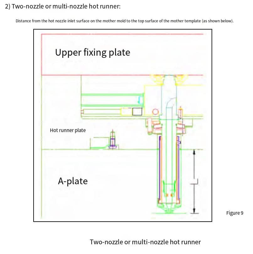
The mouth length of two or more mouths is generally fixed within a range and does not require an integer.
4.8 Other precautions:
(1) Mold selection:
The mold used for the hot nozzle mold is the same as the general form of mold, only a reasonable plate thickness needs to be selected. The hot runner mold requires the addition of a hot runner plate, so a support plate needs to be added between the mother template and the upper fixed plate. When designing, attention should be paid to the thickness of the mold. As we are currently mostly hot half molds, the hot runner part above the mother template is provided by the hot runner company. Therefore, when designing, we only need to design the mother template and the following parts.

(2) In addition, please refer to the HUSKY Hot Runner Mold Standard for the specifications and positions of the screws that fix the hot runner support plate, as well as the positions of the guide pillars in the hot runner section.
(3) When ordering a hot nozzle (single nozzle) mold, it is necessary to fill out the “Hot Runner Order Contact Form”, providing the size of the mold, the number and specifications of the hot nozzle, nozzle length, product weight, plastic material and properties table, etc.
(4) When ordering hot runner (multi nozzle) molds, in addition to the above content, attached drawings (hot nozzle plane position and screw, guide pillar position diagram) are also required. Please refer to the “Hot Runner Mold and Non standard Mold Blank Ordering”.
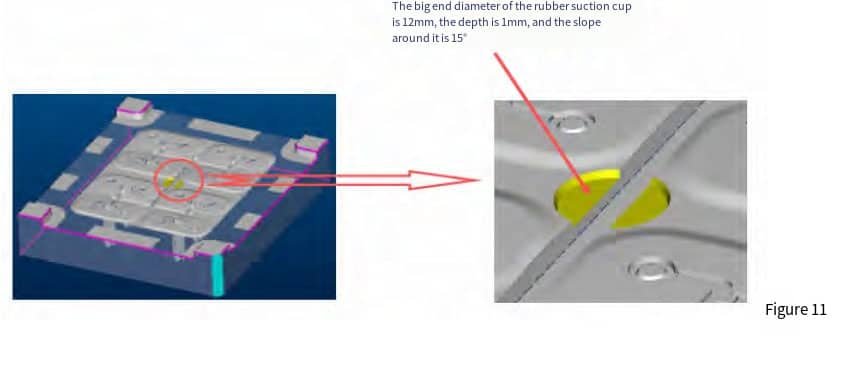
(5) Design standards for suction cups when transitioning from hot runner to cold runner.
The size of the suction cup corresponds to the size of the mechanical arm suction cup on the injection molding machine, as shown in Figure 11