To ensure that the mold can produce qualified products, be put into production normally, ensure the service life of the mold production, and meet the production and use requirements of product design, the standard for approving the mold is standardized from the aspects of product quality, mold structure, and injection molding process requirements, and the mold quality is evaluated accordingly.
Reference standard:
GB/T12554-2006 Technical Specifications for Plastic Injection Molds
GB/T4169.1~4169.23-2006 Injection mold parts
GB/T12556-2006 Technical Conditions for Plastic Injection Mold Frame
GB/T14486-2008 Dimensional Tolerance of Plastic Mouldings
I. Appearance, size and fit of molded products
- Defects are not allowed on the product surface: missing material, charring, white top, white lines, pilling, blistering, pulling white (or pulling crack, pulling break), baking printing, wrinkles.
- Weld mark: Generally, the length of the circular perforation weld mark is not more than 5mm, and the length of the irregular perforation weld mark is less than 15mm. The strength of the weld mark can pass functional safety testing.
- Shrinkage: There should be no significant shrinkage on the visible surface, and slight shrinkage (no noticeable dent) is allowed on the less visible surface.
- Variant: Generally, the flatness of small products is less than 0.3mm, and those with assembly requirements need to ensure that the assembly requirements are met.
- There should be no air bubbles or material flowers in the visible parts of the appearance, and the product should generally not have bubbles.
The geometric shape, size, and dimensional accuracy of the product should comply with the requirements of the official and valid mold drawing (or 3D file). The product tolerance should be based on the principle of tolerance, with the axis size tolerance being negative and the hole size tolerance being positive. If the customer has requirements, they should be met.
- Product wall thickness: The average wall thickness is generally required for the product wall thickness, and the non-average wall thickness should meet the drawing requirements. The tolerance should be -0.1mm according to the mold characteristics.
Product coordination: Surface shell and bottom shell coordination: Surface misalignment should be less than 0.1mm, and there should be no scratching. Holes, shafts, and surfaces with coordination requirements should ensure the coordination interval and usage requirements.
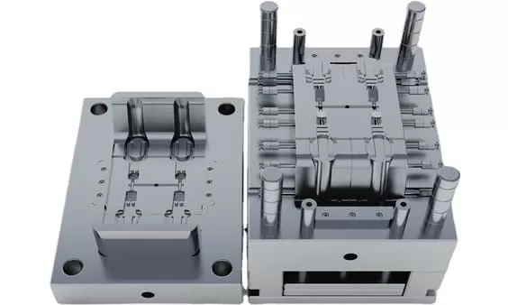
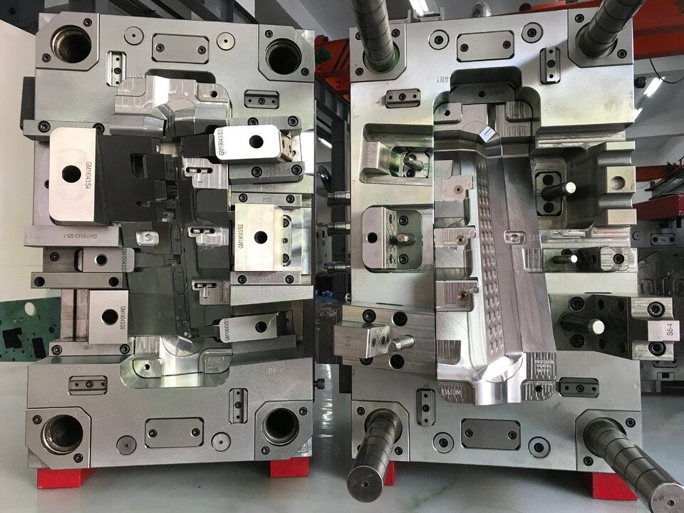
II. Mold Appearance
- The mold nameplate content is complete, the characters are clear, and the arrangement is neat.
- The nameplate should be fixed on the mold foot near the template and the reference angle. The nameplate should be securely fixed and not easily peeled off.
- The cooling water nozzle should be a plastic block nozzle, unless otherwise required by the customer.
- The cooling water nozzle should not protrude from the surface of the mold frame.
- The cooling water nozzle needs to be processed with counterbore, with three specifications of 25mm, 30mm, and 35mm in diameter. The orifice should be chamfered, and the chamfer should be consistent.
- The cooling water nozzle should have an in-out mark.
- The mark of English characters and numbers should be larger than 5/6, located 10mm directly below the faucet, and the handwriting should be clear, beautiful, neat, and evenly spaced.
- Mold accessories should not affect the lifting and storage of the mold. During installation, there should be support legs to protect exposed oil cylinders, water nozzles, and pre-reset mechanisms below.
- The installation of the support leg should be fixed to the mold frame with screws passing through the support leg. Excessive support legs can be machined with external threaded posts to secure them to the mold frame.
- The size of the mold ejection hole should meet the requirements of the specified injection molding machine. Except for small molds, it is not possible to use only one central ejection.
The locating ring should be fixed and reliable, with a diameter of 100mm or 250mm, and the locating ring should be 10-20mm higher than the base plate, unless otherwise required by the customer.
- The overall dimensions of the mold should meet the requirements of the designated injection molding machine.
- Molds with direction requirements should be marked with arrows on the front or rear templates indicating the installation direction. The word “UP” should be next to the arrow, and both the arrow and the text should be yellow with a text height of 50mm.
- The surface of the formwork should be free of pits, rust, excess lifting rings, water vapor ingress and egress, oil holes, and other defects that affect the appearance.
- The mold should be easy to lift and transport. During lifting, the mold components should not be disassembled, and the lifting ring should not interfere with the water nozzle, oil cylinder, pre-reset rod, etc.
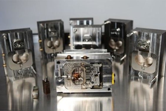
III.mold materials and hardness
- The mold frame should be selected from standard mold frames that meet the standards.
- The materials for mold forming parts and gating systems (cores, movable and fixed mold inserts, movable inserts, splitter cones, push rods, and sprue bushings) are made of materials with a performance higher than 40Cr.
- When forming plastics that are prone to corrosion in the mold, the molded parts should be made of corrosion-resistant materials, or anti-corrosion measures should be taken on their molding surfaces.
- The hardness of the molded parts of the mold should not be lower than 50HRC, or the hardness of the surface hardening treatment should be higher than 600HV.
IV.Ejection, reset, extraction and removal
- The ejection should be smooth, without stagnation or abnormal sound.
- The surface of the ram should be polished, and the ram surface should be lower than the core surface.
- The sliding parts should be provided with oil grooves, and the surface should be subjected to nitriding treatment, resulting in a surface hardness of HV700 or higher.
- All the push rods should have rotation stop positioning, and each push rod should be numbered.
- The ejection distance shall be limited by using a stop block.
- The return spring should be a standard part, and both ends of the spring should not be polished or cut.
- Sliders and core-pulling devices should have travel limits. Small sliders should be limited by springs, and when springs are not convenient for installation, wave screws can be used. Cylinder core-pulling devices must have travel switches.
- Sliding blocks are generally core-pulled using diagonal guide posts, with the angle of the diagonal guide post being 2° to 3° smaller than the angle of the locking surface of the sliding block. If the sliding block stroke is too long, it should be pulled using an oil cylinder.
- When the end face of the oil cylinder core-pulling molding part is wrapped, the oil cylinder should be equipped with a self-locking mechanism.
- A wear plate should be placed under large sliders with a width of more than 150mm. The wear plate material should be T8A, with a hardness of HRC50-55 after heat treatment. The wear plate should be 0.05-0.1mm higher than the large surface, and a oil groove should be cut.
- The top rod should not move up and down.
- Add barbs on the top bar, with the direction of the barbs consistent, and the barbs are easy to remove from the product.
The clearance between the top rod hole and the top rod, the length of the sealed section, and the surface roughness of the top rod hole should comply with the requirements of relevant enterprise standards.
- The product should be easy for the operator to remove.
- When the product is ejected, it is easy to follow the ram. The ram should be provided with grooves or etchings.
- The top block fixed on the top rod should be secure and reliable, with a 3°~5° slope on the surrounding non-molding parts, and chamfered edges on the lower part.
- The oil passage holes on the mold frame should be free of iron chips and debris.
- The end face of the return lever is smooth and free of spot welding. The bottom of the embryo head is free of gaskets and spot welding.
- The guide sliding of the third plate mold gate plate is smooth, and the gate plate is easy to pull apart.
- The limit pull rod of the three-plate mold should be arranged on both sides of the mold installation direction, or a pull plate should be added to the mold frame to prevent interference between the limit pull rod and the operator.
- The oil and air passages should be smooth, and the hydraulic ejection reset should be in place.
- The bottom of the guide sleeve should be provided with an exhaust port.
- The installation of the locating pin should not have any gap
V. Cooling and heating system
- The cooling or heating system should be fully unblocked.
- The seal should be reliable, and the system should be free of leakage under a pressure of 0.5 MPa and easy to maintain.
- The size and shape of the sealing groove on the mold base should comply with relevant standards.
- The sealing ring should be applied with butter when placed, and should be higher than the mold frame surface after placement.
- The water and oil flow passage spacer should be made of materials that are not easily corroded.
- The front and rear molds should adopt a centralized water supply method.
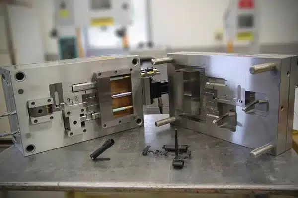
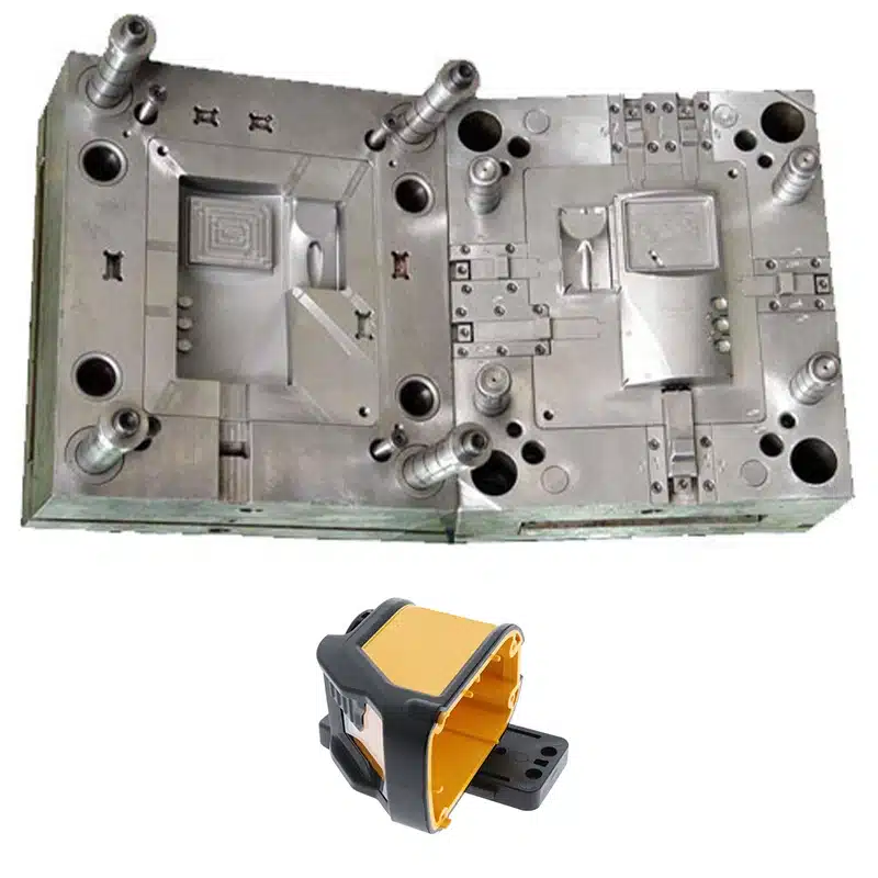
VI. Pouring system
- The gate setting should not affect the appearance of the product and meet the requirements of product assembly.
- The cross-section and length of the runner should be designed reasonably, and the process should be shortened as much as possible while ensuring the quality of the forming process. The cross-sectional area should be reduced to shorten the filling and cooling time, while minimizing the loss of plastic from the gating system.
- The section of the third plate mold sprue on the back of the front plate should be trapezoidal or semicircular.
The three-plate mold has a break on the gate plate, and the diameter of the runner inlet should be less than 3mm. The ball head has a 3mm deep step recessed into the gate plate.
- The ball-head draw rod should be reliably fixed, either under the locating ring, with a headless screw, or with a pressure plate.
- The gate and runner should be machined according to the drawing size requirements, and manual processing with a sanding machine is not allowed.
- The gate should be placed according to the specifications.
- There should be an extension at the front end of the diversion channel as a cold material pit.
- The Z-shaped back-off of the pull rod should have a smooth transition.
- The runner on the parting surface should be circular, and the front and rear molds cannot be misaligned.
- The latent gate on the ejector pin should have no surface shrinkage.
- The diameter and depth of the cold material cavity of transparent products should meet the design standards.
- The material is easy to remove, the appearance of the product has no gate marks, and there is no residual material at the assembly site of the product.
- The hook-type latent gate, with two parts of insert, should be nitrided to achieve a surface hardness of HV700.
VII. Hot runner system
The layout of hot runner wiring should be reasonable and easy to maintain, and the wiring numbers should correspond one-to-one.
- The hot runner should be tested for safety, with ground insulation resistance greater than 2MW.
- The temperature control cabinet, hot nozzle, and hot runner should use standard parts.
- The mainstream muzzle is connected with a thread and a hot runner, with the bottom plane in contact for sealing.
- The hot runner is in good contact with the heating plate or heating rod, and the heating plate is fixed with screws or studs, with a good surface fit.
- J-type thermocouples shall be used and matched with temperature control meters.
- Each group of heating elements should be controlled by thermocouples, and the location of the thermocouples should be reasonably arranged.
- The nozzle should meet the design requirements.
- The hot runner should be reliably positioned, with at least two locating pins or secured with screws.
- There should be thermal insulation pads between the hot runner and the template.
The error between the set temperature and the actual displayed temperature of the temperature control meter should be less than ±5°C, and the temperature control should be sensitive.
- The cavity and nozzle mounting holes should be penetrated.
- The hot runner wiring should be bundled and covered with a pressure plate.
- There should be clear markings for two sockets of the same specifications.
- The control line should have a sheath and be free of damage.
- The temperature control cabinet has a reliable structure and the screws are not loose.
- The socket is installed on the bakelite board, and cannot exceed the maximum size of the template.
- The wire is not allowed to be exposed outside the mold.
- All contact points between the hot runner or template and the wire should have rounded corners for transition.
- Before assembling the template, all the lines should be free of open circuit and short circuit.
- All wiring should be properly connected and have good insulation performance.
After the template is clamped, all lines should be checked again with a multimeter.
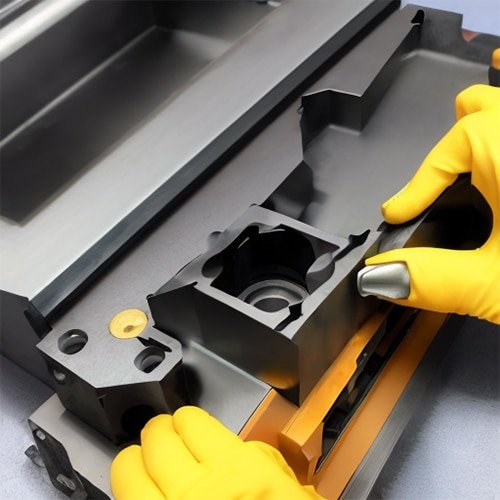
VIII. Forming part, parting surface, exhaust groove
- The surfaces of the front and rear molds should be free of irregularities, pits, rust, and other defects that affect the appearance.
- The insert should fit with the mold frame, with a gap of less than 1mm around the rounded corners.
- The parting surface should be kept clean and tidy, without any hand-held grinding wheel marks, and the sealed part should be free of depressions.
- The depth of the exhaust slot should be less than the plastic overflow value.
- The fitting of the insert should be in place, smoothly placed, and reliably positioned.
- The insert and core should be reliably positioned and fixed, and the circular parts should have a rotation stop. Do not place copper or iron sheets under the insert.
- The end face of the top rod is consistent with the core.
- The front and rear mold forming parts are free of defects such as buckling and chamfering.
- The extrusion of the rib should be smooth.
- For products with multi-cavity molds, the left and right pieces should be symmetrical and marked with L or R. If customers have requirements for position and size, they should be met. Generally, this is added in places that do not affect the appearance and assembly, with a font size of 1/8.
- The locking surface of the formwork should be properly fitted, with more than 75% of the area touching.
- The top bar should be arranged near the side wall and next to the ribs and bosses, and a larger top bar should be used.
- The same parts shall be marked with numbers 1, 2, 3, etc.
- The contact surface, insertion surface and parting surface should be fitted properly.
- The sealing part of the parting surface should meet the design standards. The mold for medium and smaller sizes should be 10-20mm, and the mold for large sizes should be 30-50mm. The rest of the part should be machined to avoid voids.
- The texture and sandblasting should be evenly applied to meet customer requirements.
- For products with appearance requirements, the screws on the product should have anti-shrinkage measures.
- The screw column with a depth of more than 20mm should be used with a pipe jacking method.
- The wall thickness of the product should be uniform, with a deviation controlled below ±0.15mm.
- The width of the rib should be less than 60% of the wall thickness of the appearance surface.
- The core in the ram and slider should be fixed reliably.
- When the front mold is inserted into the rear mold or vice versa, there should be a beveled locking surface around the perimeter and machined to avoid voids.
Injection molding production process
- The mold should have stability in injection molding production and repeatability in process parameter adjustment within the normal injection molding process conditions.
- The injection pressure during mold injection production should generally be less than 85% of the rated maximum injection pressure of the injection molding machine.
- During the injection molding production of the mold, the injection speed of three-quarters of the stroke shall not be less than 10% of the rated maximum injection speed or exceed 90% of the rated maximum injection speed.
The packing pressure during mold injection production should generally be less than 85% of the actual maximum injection pressure.
- The clamping force during mold injection production should be less than 90% of the rated clamping force of the applicable model.
- During the injection molding process, the removal of products and scrap materials should be easy and safe (typically no more than 2 seconds each).
- For molds with inserts, it is convenient to install the inserts during production and the inserts should be reliably fixed.
X. Packaging and Transportation
- The mold cavity should be cleaned and sprayed with anti-rust oil.
- The sliding parts should be coated with lubricating oil.
- The feed inlet of the sprue bushing should be blocked with grease.
- The mold should be equipped with a clamping plate, with specifications meeting design requirements.
- Spare parts and vulnerable parts should be complete, with a detailed list and supplier name attached.
- Sealing measures should be taken at the inlet and outlet of the mold water, liquid, gas, and electricity to prevent foreign objects from entering;
- Spray paint on the external surface of the mold, as required by the customer.
- Packaging should be moisture-proof, waterproof, and collision-proof, and should be made according to customer requirements.
- The drawings of mold products, structural drawings, cooling and heating system drawings, hot runner drawings, details of suppliers of spare parts and mold materials, instructions for use, report on trial molding, factory inspection certificate, and electronic documents should be complete.
XI. Acceptance Judgment
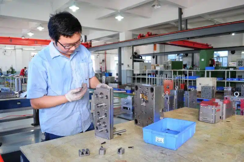
- The mold should be inspected and accepted one by one according to the requirements of this standard, and the acceptance records should be kept.
- The acceptance judgment is divided into qualified items, acceptable items, and unacceptable items. If all items are qualified or acceptable, the mold is considered to be qualified.
- Number of unacceptable items: 1 product; 1 mold material; 4 mold appearances; 2 ejector reset plugs; 1 cooling system; 2 pouring systems; 3 hot runner systems; 3 molding parts; 1 production process; 3 packaging and transportation; the mold is determined to need rectification.
- Number of unacceptable items: More than 1 item for the product; more than 1 item for the mold material; more than 4 items for the mold appearance; more than 2 items for the ejection reset and plunging core; more than 1 item for the cooling system; more than 2 items for the pouring system; more than 3 items for the hot runner system; more than 3 items for the molding part; more than 1 item for the production process; more than 3 items for packaging and transportation; it is determined as a non-conforming mold.