With the rapid development of the mold industry in recent years, and the continuous expansion and progress of the application scope of new technologies and processes, there has been a qualitative change from traditional experience accumulation to software development applications.
The wide application of CAD, CAM and CAE has opened up room for improvement in the geometric dimension control technology of our molds and mold products. Due to the significant differences in market demand and the wide variety of molds and mold products, as well as the high requirements for changes in shape, size, material, structure, and other aspects, we have encountered many problems and difficulties in the production process of molds and products. Among them, how to effectively control the geometric dimensions of molds and products is also very intuitive for us.
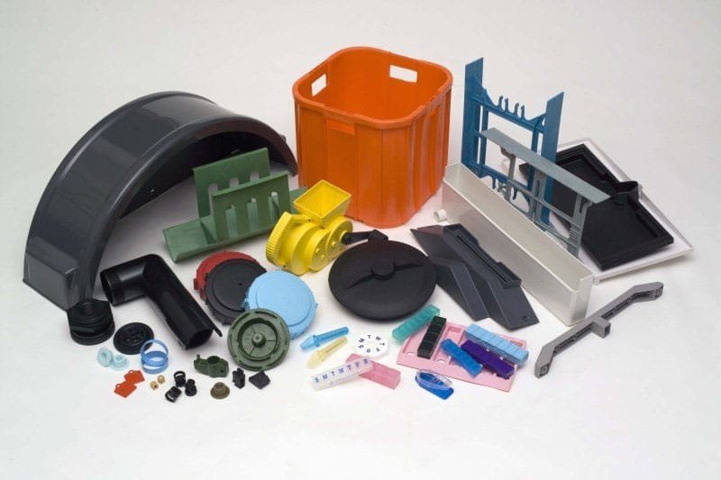
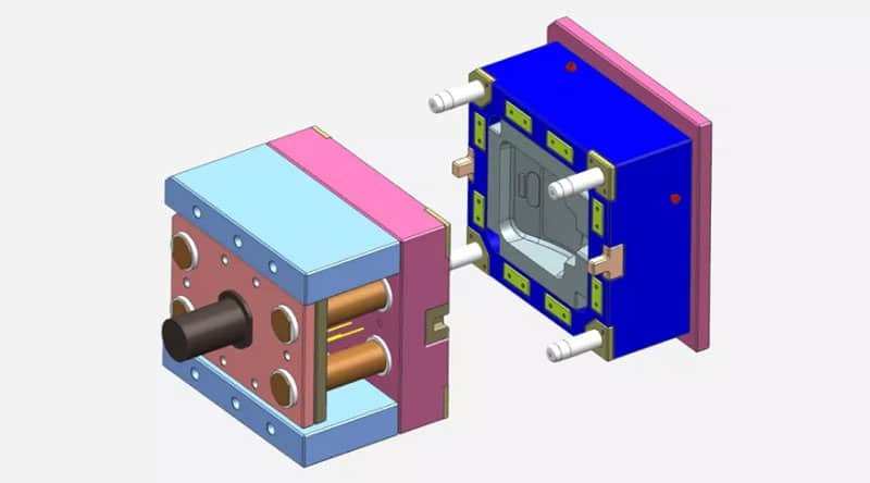
Different types of molds and products have different control techniques and methods. Today, I would like to share some insights on the dimensional control of injection molded products. When it comes to injection molded products, we inevitably discuss injection molds. Generally, I approach it from the following aspects.
I. Control of mold design
Firstly, it is necessary to fully understand the technical requirements of users in terms of mold structure, materials, hardness, and precision, including whether the shrinkage rate of the molded plastic material is correct, whether the 3D dimensional modeling of the product is complete, and whether it is processed and analyzed reasonably.
2. Take full account of various places that affect the appearance of injection molded products, such as shrinkage, flow marks, mold slope, weld lines, and cracks.
3. Simplify the mold processing method as much as possible without hindering the function and pattern of the injection molded product.
4. Whether the selection of the parting surface is appropriate, and careful selection should be made for mold processing, forming appearance, and deburring of the formed parts.
5. Whether the pushing method is appropriate, whether it is by using push rods, discharge plates, push sleeves, or other methods, and whether the position of the push rods and discharge plates is appropriate.
6. Whether the use of the side core-pulling mechanism is appropriate, the action is flexible and reliable, and there should be no clamping stagnation.
7. What method is more suitable for temperature control of plastic products? What structure circulation system is used for temperature control oil, temperature control water, cooling liquid, etc.? Is the size, quantity, and location of the cooling liquid holes appropriate.
8. The form of the gate, the size of the material channel and the feed inlet, and whether the position and size of the gate are appropriate.
9. Whether the heat treatment deformation of various modules and mold cores and the selection of standard parts are appropriate.
10. Whether the injection volume, injection pressure and clamping force of the injection molding machine are sufficient, and whether the nozzle R, gate sleeve aperture, etc. are properly matched.
Comprehensive analysis and preparation should be carried out in these aspects, and strict control should be exercised from the initial stage of product development.

II. Control of process manufacturing
Although we have fully considered and arranged during the design stage, there will still be many problems and difficulties in actual production. We should try our best to meet the original intention of the design in production and find more effective and economical process methods in actual processing.
1. Select economical and adaptable machine tools for 2D and 3D processing schemes.
2. Appropriate tooling fixtures can also be considered for auxiliary preparation work during production, and the rational use of cutting tools can prevent deformation of product parts, prevent fluctuations in the shrinkage rate of product parts, prevent demolding deformation of product parts, improve the accuracy of mold manufacturing, reduce errors, prevent changes in mold accuracy, and so on. A series of production process requirements and solutions.
3. Here, we would like to mention the causes of dimensional errors in the forming parts of the British Plastics Federation (BPF) and their proportion distribution:
A: Manufacturing error accounts for approximately 1/3, B accounts for approximately 1/6 due to mold wear, C accounts for roughly one-third of uneven shrinkage of molded parts, and D covers discrepancies between predetermined shrinkage rate and actual shrinkage rate.
As A + B + C + D equals total error, it can be seen that tolerance of mold manufacturing should fall within 1/3 of the total tolerance of formed part, otherwise achieving geometric dimensions will be challenging for mold.
III. Production Control
The fluctuation of geometric dimensions after the formation of plastic parts is a common problem and often occurs:
1. Control of material temperature and mold temperature
Different grades of plastics require different temperature requirements. The use of plastics with poor fluidity and mixtures of two or more types can lead to different situations. It is important to control the plastic material within the optimal flow range. These are usually easy to achieve, but the control of mold temperature is more complex. Different geometric shapes, sizes, and wall thickness ratios of the molded parts have certain requirements for the cooling system. The mold temperature largely controls the cooling time;
Therefore, try to keep the mold at an allowable low temperature to shorten the injection cycle and improve production efficiency. If the mold temperature changes, the shrinkage rate will also change. Keeping the mold temperature stable will also stabilize the dimensional accuracy, thus preventing defects such as deformation, poor gloss, and cooling spots in the molded part, and maintaining the physical properties of the plastic at their optimal state. Of course, there is also a debugging process, especially for multi-cavity mold parts which are more complex.

2. Adjustment and control of pressure and exhaust:
The appropriate injection pressure and matching clamping force should be determined during mold debugging. The air and plastic gases generated in the gaps formed by the mold cavity and core must be discharged from the exhaust slot outside the mold. If the exhaust is not smooth, insufficient filling, weld marks, or burns may occur. These three forming defects sometimes occur in the same location occasionally;
When there is a thick wall around the thin wall part of the formed part, insufficient filling will occur if the mold temperature is too low, and burns will occur if the mold temperature is too high. Usually, there will be weld marks at the burned area, and the exhaust groove is often overlooked and generally in a small state. Therefore, as long as there is no burr, the depth of the exhaust shoulder should be as deep as possible, and a large vent groove should be opened at the rear of the shoulder to allow the gas behind the shoulder to be quickly discharged out of the mold. If there is a special need, an exhaust groove can be opened on the ejector pin. The principle is the same: first, no burrs will occur, and second, the gas can be quickly discharged to achieve good results.
3. Supplementary shaping control of injection molded parts dimensions
Due to different shapes and sizes, some plastic parts may deform and warp after demolding due to changes in temperature and pressure loss. In this case, auxiliary fixtures can be used for adjustment, and timely and rapid remedial measures can be taken after the molded parts are ejected from the mold. After natural cooling and setting, better correction and adjustment effects can be achieved. If strict management is ensured throughout the injection molding process, the dimensions of the injection molded parts can be very well controlled.