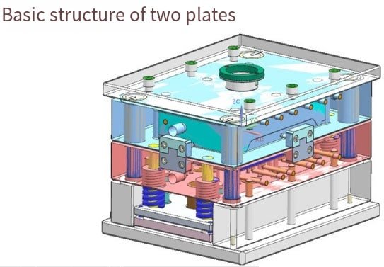
An injection mold consists of two parts, the moving mold and fixed mold. Both components are installed onto their respective templates on an injection molding machine for installation; during injection molding, both molds close together to form the gating system and cavity before being opened up to extract plastic product from each one of them.
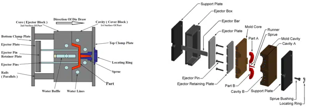
The structure of Plastic Molds may vary widely due to differences in plastic variety, performance and structure; product shape/structure; injection machine type; however the basic framework remains consistent. A plastic mold primarily comprises of casting system, temperature control system, mold parts and structural parts with casting system/mold parts being the parts which come into direct contact with plastic and can vary with it and product – these require highly smooth processing with accuracy for smooth processing results.
The pouring systems, more commonly referred to as runners systems, are feeding channels which move plastic melt from an injection machine nozzle into mold cavities. They typically consist of main flow channels, diversion channels, gates, and cold material cavities – each of which plays an essential role in improving molding quality and production efficiency of plastic products.
Pouring system
The pouring system, also known as the runner system, is a set of feeding channels that guide plastic melt from the injection machine nozzle to the mold cavity. It is usually composed of a main flow channel, a diversion channel, a gate, and a cold material cavity. It is directly related to the molding quality and production efficiency of plastic products.

- Mainstream channel
It is a passage in the mold that connects the injection machine nozzle to the diversion channel or cavity. The top of the main channel is concave to facilitate connection with the nozzle. The inlet diameter of the main channel should be slightly larger than the nozzle diameter (O.8mm) to avoid overflow and prevent blockage caused by inaccurate connection between the two. The import diameter depends on the size of the product, usually 4-8mm. The diameter of the main channel should be expanded inward at an angle of 3 ° to 5 ° to facilitate demolding of the channel debris.
- Cold material hole
It is a cavity located at the end of the main stream to capture the cold material generated between two injections at the nozzle end, thereby preventing blockage of the splitter or gate. If the cold material is mixed into the mold cavity, it is easy to generate internal stress in the produced product. The diameter of the cold material hole is about 8-10mm, with a depth of 6mm.
For the convenience of demolding, its bottom is often supported by the demolding rod. The top of the demoulding rod should be designed in a zigzag hook shape or with a sunken groove, so that the main channel debris can be smoothly pulled out during demoulding.

- Diversion channel
It is a channel that connects the main channel and various cavities in a multi slot mold. To ensure that the molten material fills the various cavities at an equal speed, the arrangement of the diversion channels on the plastic mold should be symmetrical and equidistant.
The shape and size of the diversion channel section have an impact on the flow of plastic melt, the difficulty of product demolding, and mold manufacturing. If the flow rate is equal to the amount of material, the resistance of the circular cross-section channel is the smallest.
However, due to the small surface area of the cylindrical flow channel, it is not conducive to cooling the debris in the flow channel, and this type of flow channel must be opened on the two halves of the mold, which is both labor-intensive and easy to align. Therefore, trapezoidal or semi-circular cross-sectional flow channels are often used and are set on half of the mold with a release rod.
The surface of the runner must be polished to reduce flow resistance and provide a faster filling speed. The size of the runner depends on the type of plastic, the size and thickness of the product. For most thermoplastic materials, the cross-sectional width of the diversion channel does not exceed 8m, with oversized ones reaching 10-12m and particularly small ones ranging from 2-3m. On the premise of meeting the needs, the cross-sectional area should be minimized as much as possible to avoid adding debris to the diversion channel and prolonging the cooling time.
- Gate
It is a channel that connects the main channel (or diversion channel) to the cavity. The cross-sectional area of the channel can be equal to that of the main channel (or diversion channel), but it is usually reduced. So it is the part with the smallest cross-sectional area in the entire flow channel system. The shape and size of the gate have a significant impact on the quality of the product.
The function of a gate is to:
Control material flow speed
Prevent backflow during injection due to early solidification of the molten material stored in this area.
By subjecting the passing molten material to strong shear and increasing temperature, the apparent viscosity is reduced to improve fluidity.
Easy to separate the product from the flow channel system. The design of gate shape, size, and position depends on the properties of the plastic, the size and structure of the product.

The cross-sectional shape of a general gate is rectangular or circular, and the cross-sectional area should be small while the length should be short. This is not only based on the above effects, but also because it is easier for small gates to become larger, while it is difficult for large gates to shrink. The gate position should generally be selected at the thickest part of the product without affecting its appearance. The design of gate size should take into account the properties of plastic melt. The cavity is the space in the mold where plastic products are formed.
The components used to form the cavity are collectively referred to as formed parts. Each formed part often has a dedicated name. The formed parts that form the shape of the product are called concave molds (also known as female molds), and the parts that form the internal shape of the product (such as holes, grooves, etc.) are called core or convex molds (also known as male molds). When designing molded parts, the overall structure of the cavity should be determined based on the performance of the plastic, the geometric shape of the product, dimensional tolerances, and usage requirements.
Secondly, the position of the parting surface, gate, and exhaust hole, as well as the demolding method, should be selected based on the determined structure. Finally, design each part according to the size of the control product and determine the combination method between each part.
When plastic melt enters the mold cavity, there is a high pressure, so the formed parts need to undergo reasonable material selection and strength and stiffness verification. To ensure the smooth and beautiful surface of plastic products and easy demolding, any surface in contact with plastic must have a roughness Ra>0.32um and be corrosion-resistant. Formed parts are generally improved in hardness through heat treatment and made of corrosion-resistant steel.
Temperature control system
In order to meet the temperature requirements of the injection process for the mold, a temperature control system is needed to adjust the temperature of the mold. For injection molds for thermoplastic materials, the main approach is to design a cooling system to cool the mold.
The common method of mold cooling is to set up a cooling water channel inside the mold, and use the circulating cooling water to take away the heat of the mold; In addition to using cooling water channels for hot water or steam, electric heating elements can also be installed inside and around the mold for heating.
Formed components
The formed component consists of a core and a die. The core forms the inner surface of the product, while the concave mold forms the outer surface shape of the product. After the mold is closed, the core and cavity form the cavity of the mold. According to the requirements of technology and manufacturing, sometimes the core and die are composed of several assembled blocks, and sometimes they are made into a whole. Only inserts are used in areas that are prone to damage and difficult to machine.
The exhaust port is a groove shaped air outlet opened in the mold to discharge the original gas and the gas brought in by the molten material. When the molten material is injected into the mold cavity, the air originally stored in the cavity and the gas brought in by the molten material must be discharged out of the mold through the exhaust port at the end of the material flow. Otherwise, it will cause the product to have pores, poor connections, insufficient mold filling, and even the accumulated air to be compressed and generate high temperature, which will burn the product.
In general, the exhaust hole can be located at the end of the molten material flow in the mold cavity or on the parting surface of the plastic mold.
The latter involves opening a shallow groove on one side of the concave mold, with a depth of 0.03-0.2mm and a width of 1.5-6mm. During injection, there will not be a lot of molten material seeping out of the exhaust hole, as the molten material will cool and solidify at that location, blocking the channel. The opening position of the exhaust port should not face the operator to prevent accidental spraying of molten material and injury. In addition, the clearance between the ejection rod and the ejection hole, as well as the clearance between the ejection block, the template, and the core can also be used for exhaust.
Structural components
It refers to various parts that make up the mold structure, including guiding, demolding, core pulling, and parting parts. Such as front and rear clamp plates, front and rear buckle templates, pressure plates, pressure columns, guide columns, release templates, release rods, and return rods.
- Guiding components
To ensure accurate alignment between the moving and fixed molds during mold closing, guide components must be installed in the mold. In injection molding, four sets of guide pillars and guide sleeves are usually used to form a guide, and sometimes matching inner and outer conical surfaces need to be set on the moving and fixed molds to assist in positioning.
- Launching institutions
During the mold opening process, a push out mechanism is required to push out or pull out the plastic products and their aggregates in the flow channel. Push out the fixed plate and push plate to clamp the push rod. There is usually a reset rod fixed in the push rod, which resets the push plate when moving or fixing the mold.
- Side core pulling mechanism
Some plastic products with concave or perforated sides must be laterally divided before being pushed out, and the lateral core must be extracted before the mold can be smoothly demolded. In this case, a lateral core extraction mechanism needs to be set up in the mold.
- Standard mold base
In order to reduce the heavy workload of mold design and manufacturing, most injection molds use standard mold frames.