Plastic injection mold, more commonly referred to as injection mold, is a production tool capable of mass-producing plastic parts or products in large volumes. Injection molds work by molding one or more cavities formed from assembled parts into their desired shapes to produce plastic parts with greater ease. They are one of the most widely-used mold types with complex structures and the highest design, manufacturing, and processing precision among all plastic molds.
Classification of injection Mold
There are various methods for classifying injection molds. One way is based on their basic structure of injection mold casting systems: two-plate mold (also referred to as large nozzle mold), three-plate mold (fine nozzle mold), and hot runner molds (also called no-flow molds).
Two-plate formwork
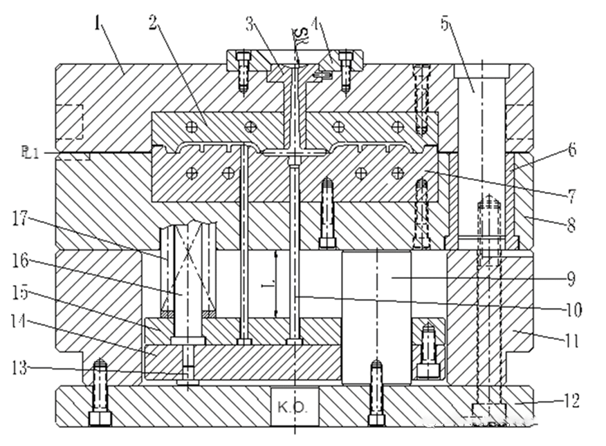
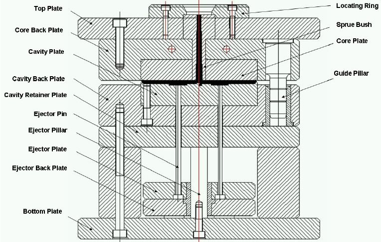
Two-plate mould is commonly known as big nozzle mould or single-split mould. See Fig. 1-1 for typical structure. Two-plate mold is the simplest and most widely used mold in injection molding. It divides the whole mold into moving mold and fixed mold with the parting surface as the boundary.
(1) K Hole O shall not be less than the ejector rod diameter of injection molding machine;
(2) The pushing stroke L shall ensure that the plastic parts can be completely separated;
(3) When automatic injection molding production is required, ensure that the plastic parts and the pouring system condensate can be completely and safely removed from the mold cavity; In semi-automatic or manual mode, the plastic parts shall be taken out easily;
(4) The spherical radius SR of the gate bushing must be greater than the nozzle radius of the injection molding machine.
3-Plate-Mold
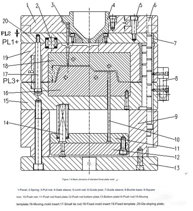
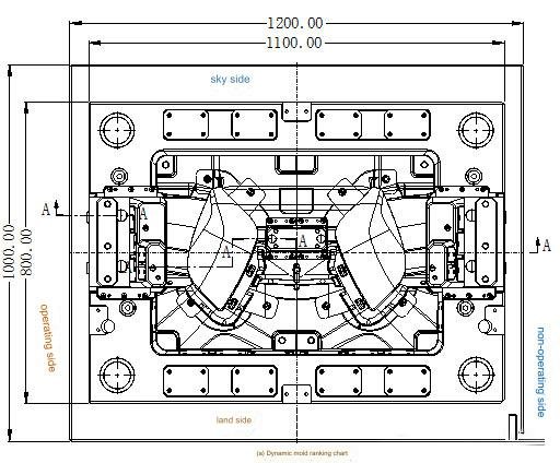
Three-plate Mold is commonly known as fine nozzle die or double parting surface die. Three-plate die is divided into three parts after die opening, and a stripper plate (commonly known as nozzle plate) is added compared with two plate dies. It is applicable to the situations where there is no gate trace around the plastic parts or the projected area is large, and multi-point feeding is required. This kind of die adopts point gate, the structure is more complex, and the fixed distance parting mechanism needs to be designed.
Attention shall be paid to the design of standard three-plate mold:
B ≥ S1+S2+20~30;
B ≥ 100;
L ≥ A+B;
A shall be 8-12mm
Other precautions are the same as those of the second plate die.
Where: A – mould opening distance of parting surface 2;
B – mould opening distance of parting surface 1;
S1 – length of main flow path;
S2 – length of bypass;
Simplified three-plate die:
Since the simplified three-plate mold reduces four dynamic mold guide posts compared with the standard three-plate mold, the fixed mold guide post must guide the stripper plate, fixed mold plate A and dynamic mold plate B at the same time, L ≥ A+B+20, and other precautions are the same as the standard three-plate mold.
The accuracy and rigidity of simplified three-plate die are poorer than that of standard three-plate die, and the service life of simplified three-plate die is less than that of standard three-plate die.
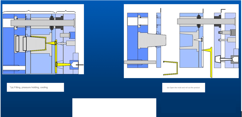
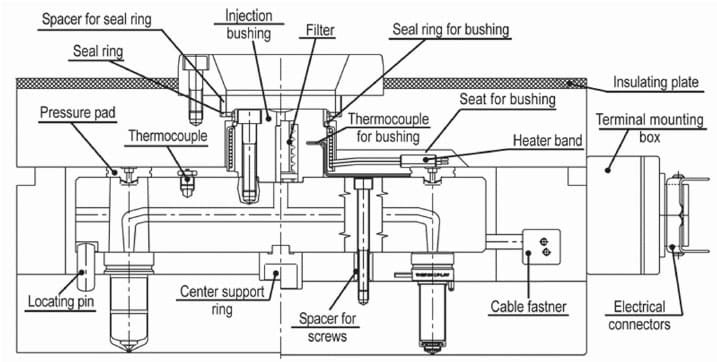
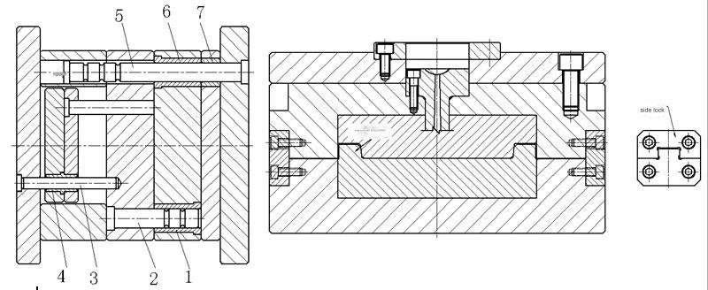
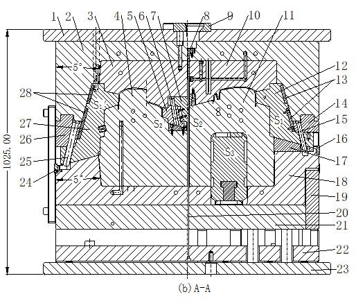
Hot runner mould
Hot runner mold is also known as no-flow mold. The hot runner mold has the advantage of simple action of the two-plate mold and the advantage that the three-plate mold melt can enter from any point in the mold cavity. Combined with the pressure, temperature and time loss of melt in the hot runner mold, it not only improves the molding quality of the mold, but also shortens the molding cycle of the mold, which is a major innovation in the injection mold pouring system technology.
Secondary hot nozzle; Locating ring; Primary thermal nozzle; Hot runner plate; Pressing block; Pull hook; Blocks; Spring; Push block; Top rod connecting column; Push rod plate guide post; Limit nail; Base plate; Movable core base plate; Movable core fixing plate; Reset lever base plate; Fixing plate of reset lever; Fixed core; Movable core; Spring; Reset lever; Supporting plate; Movable template; Fixed die inserts; Fixed template; Secondary thermal nozzle fixing plate; Support plate; Panel
Basic composition of injection mould
The injection molding system mainly consists of a pouring system, a molding system, a lateral core extraction system, a ejection and reset system, a temperature control system, an exhaust system and a guiding and positioning system.
Forming system
The forming part is a part constituting the mould cavity, including an inner mould insert, a mould core and a side extracting core. The inner mould insert comprises a female mould and a male mould, and they are parts that give shape and size to the forming plastic part.
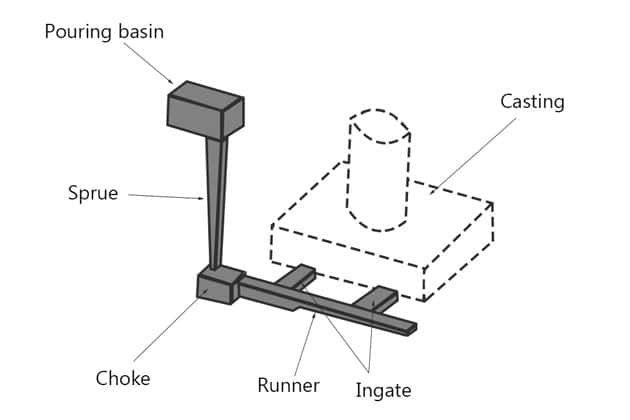
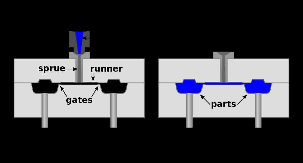
gating system
The pouring system is a transition passage before the melt in the mold enters the mold cavity, and its function is to guide the molten plastic from the injection molding machine nozzle to the closed mold cavity. Including main flow passage, branch flow passage, gate and cold material cavity. In addition to the cold runner pouring system, there is also a hot runner pouring system.
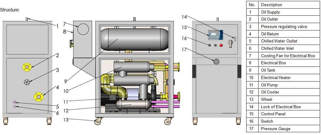
Temperature control system
This part of the structure that controls the die temperature within a reasonable range is called the temperature control system. It includes both cooling and heating, but most are cooled. The temperature control system of injection mould includes cooling water pipe, cooling water well, beryllium copper cooling, etc. The temperature control medium includes water, oil, beryllium copper and air, etc.
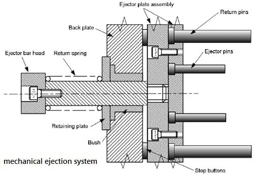
Ejection reset system
The demolding system, also known as the ejection system or ejection system, is a mechanism to realize the plastic parts to be safely detached from the die without damage. Its structure is complex and the forms are varied. The most commonly used ones are push rod pushing, push tube pushing, push plate pushing, pneumatic pushing, automatic thread demolding and compound pushing.
Guidance and positioning system
The guiding and positioning system consists of a guiding system and a positioning system. The guiding system mainly includes a guide post guide sleeve of a moving and fixed mold and a guide slot of a lateral core extracting mechanism; The positioning system mainly includes side lock and conical positioning structure, etc.
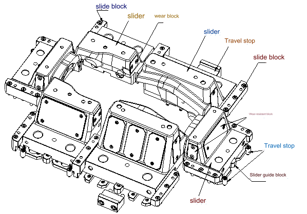
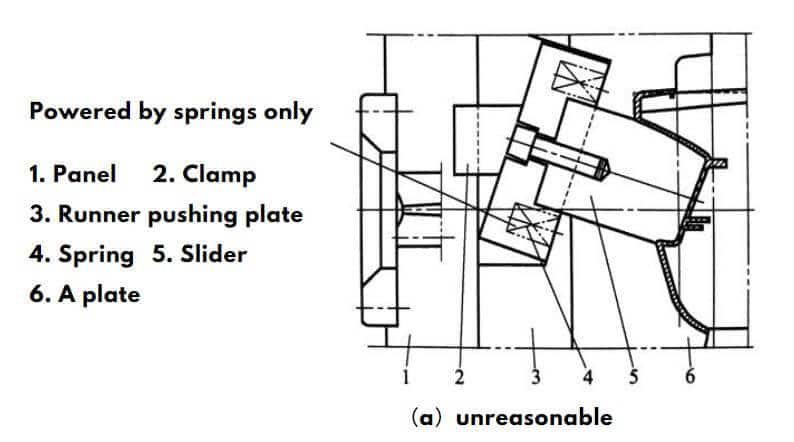
Side core withdrawal system
When there are convex-concave and hole structures on the lateral side of the plastic part, the lateral core (or insert) must be pulled out before the plastic part is pushed out, so that the plastic part can be demoulded smoothly. The lateral core extracting mechanism includes: oblique guide post, sliding block, oblique sliding block, oblique push rod, bend pin, T-shaped buckle, hydraulic cylinder, spring and other positioning parts.
exhaust system
The exhaust system is a mold structure that ejects air from the mold cavity when the melt is filled and allows air to enter the mold cavity in time when the mold is opened to avoid vacuum. Generally, the structure that can exhaust can also intake air. Exhaust modes include parting surface exhaust, exhaust trough exhaust, insert exhaust, push rod exhaust, exhaust needle exhaust, breather metal exhaust, exhaust plug exhaust, etc.