Introduction
The automotive headlamp reflector (also known as reflector) is a part of the automotive headlamp lighting system that can reflect to avoid direct light. It is located inside the lens and the decorative frame and assembled with the lens. The reflector can be seen from the outside of the lamp through the lens. Plastic parts are appearance parts with aluminized surface, and belong to high-gloss electroplating parts. The outer surface has a large area of pattern for surface decoration. The vehicle lamp is an indispensable safety device and decorative part of the vehicle. Due to the high temperature working environment and the reflection and concentration effect, the reflector needs to adopt the prefabricated monolithic molding compound (BMC) thermoset plastic molding with shrinkage rate of almost 0, heat resistance, flame retardance and strong creepage resistance. Die casting process has been adopted for this kind of material before. Due to low production efficiency, high scrap rate and harmful to human body, frequent manual reclaiming and weighing processes are required in die casting production, which brings certain dangers to the health of operators. Therefore, it has become an inevitable trend to develop the injection molding process of BMC materials to replace the die casting process.
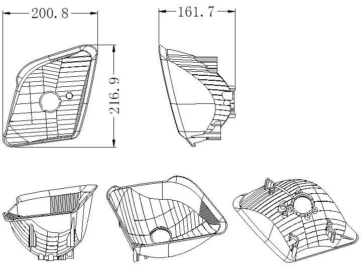
Taking automobile headlamp reflector parts as an example, this paper introduces the design key points and technical summary of automobile headlamp reflector injection mould in detail. Parts of headlamp reflector are shown in Figure 1:
1.Appearance requirements and structure analysis of plastic parts
Figure 1 shows the part drawing of headlamp reflector of a certain brand of automobile. The material is BMC, belonging to thermoset plastic. This material is very rigid, with almost zero shrinkage, and no shrinkage is required during die design. Because it is a super hard plastic, with high dimensional accuracy, good processing performance and other advantages, the disadvantage is poor mobility. Outer surface of plastic parts shall be plated (generally aluminized). Plastic parts are appearance parts with high surface requirements.
Size of plastic parts: 216.9 × 200.8 × 161.7mm. Structural features of plastic parts are as follows:
1) The appearance shall be of high requirements, and the appearance shall be free of spots, gate marks, shrinkage dents, welding marks, fins and other defects.
2) Plastic parts are electroplating parts with strict light distribution requirements, and the appearance is aluminized. The design of demolding slope of appearance surface shall be reasonable, generally at least 5 °.
3) The plastic parts have complex shape, high surface finish, no inverted buckle inside and outside the plastic parts, no need to pull the core laterally, and the plastic parts are left and right mirror parts.
2.Injection molding process of BMC material
The refrigerated BMC material is fed into the barrel of the injection molding machine dedicated to the production of BMC material, the shear heat is generated by the rotation of the screw to melt it at a lower temperature (25 ° C), and then the gelled material is injected under high pressure into a mould which is preheated up to 140-160 ° C. Under the action of high temperature, carry out chemical reaction, solidify and form after pressure maintaining, take out the mould to form plastic parts, blow off the burr and debris in the mould cavity with air gun, and then carry out the next cycle of mould assembly.
Mould structure analysis
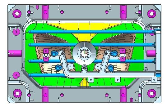
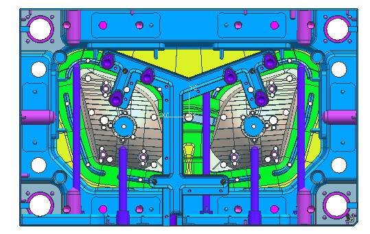
The automotive headlamp reflector is left and right mirror parts, the number of mold cavity is 1+1, and the mold adopts the cold runner pouring system. There is no inverted buckle inside and outside the plastic part, so there is no lateral core extracting mechanism. Dimension of mould: 700 × 500 × 568 (mm), total weight: about 1t, belonging to medium injection mould. See Fig. 2 – Fig. 4 for detailed structure.
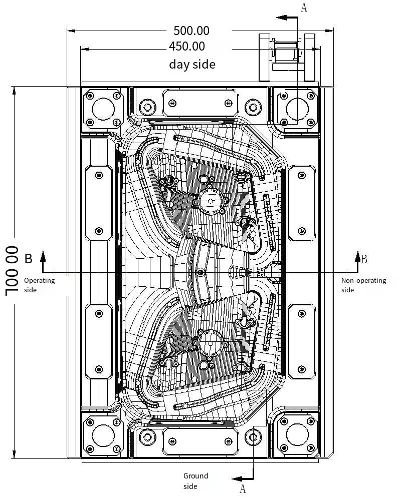
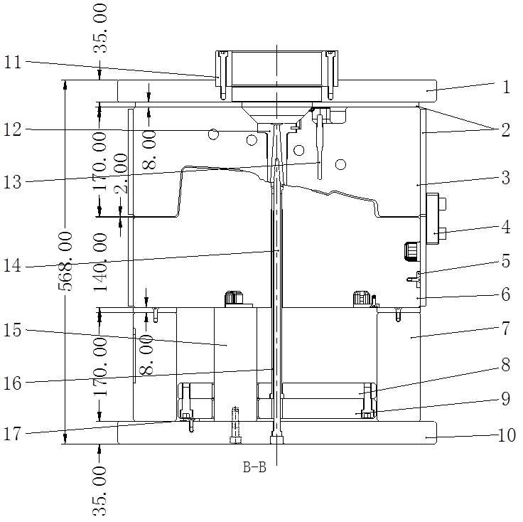
Fig. 3 Structure of Injection Mould for Headlight Reflector
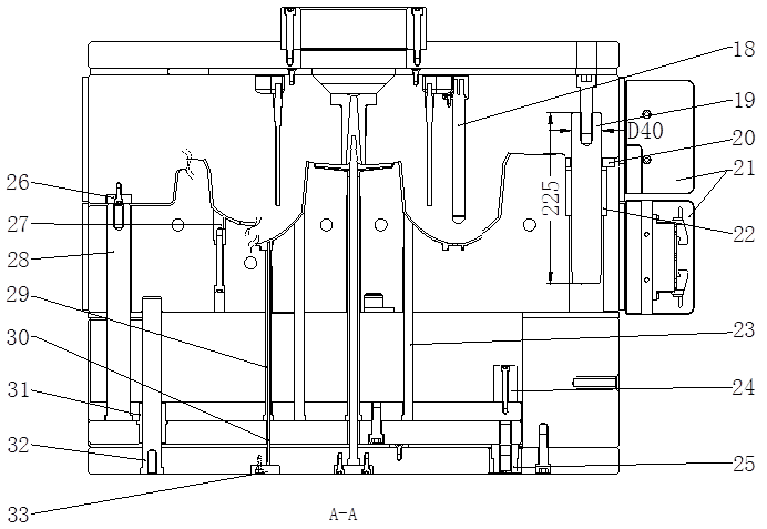
Panel; Heat insulation panel; Plate A; Lock module; Pressing block; B plate; Square iron; Push rod fixing plate; Push rod base plate; Bottom plate; Locating ring; Nozzle; Temperature sensing needle; Push the tube needle; Supporting column; Push the pipe; Garbage nailing; Heating tube 19. Guide column; Bearing plate; Junction box protection block; Guide sleeve; Push rod; Limit block; Pull reset; Quick reset; Moving die inserts; Reset lever; Push pipe sleeve; Push the tube needle; Guide sleeve of push rod plate; Push rod plate guide post; Pusher needle pressing block;
FIGS. 2, 3 and 4 show a mold structure of a headlamp reflector of an automobile. Its basic structure is similar to thermoplastic injection mould, but compared with the latter, it has the following typical differences and characteristics:
(1) Inversion of mould
Inversion of mould mentioned here is not inversion of mould. Generally, the mould cavity is set in the fixed mould and the mould core is set in the moving mould. As the plastic core of reflector is a multi-surface reflection and concentration working surface, it requires very low roughness, and ejection devices such as push rod cannot be set. Therefore, the mould must be inverted, i.e. the protruding core (working surface of reflector) is set in the fixed mould, and the recessed mould cavity is set in the moving mould.
(2) The mould shall be heated by heating tube and temperature shall be controlled strictly
The injection molding process of BMC material is completely different from the common thermoplastic injection molding process. The barrel of the injection molding machine needs to be cooled by special ice water chiller, while the core in the mold cavity needs to be heated by electricity.
The total power W of the electric heating tube required by the fixed and dynamic modes can be calculated by the following formula:
W=Gcp (Tm-To)/3600yt
G: Total weight of fixed and movable moulds, kg
Cp: specific heat capacity of mould material, kj/(kg. ° C)
Tm: temperature required for mould forming: ° C
To: room temperature: ° C
y: Efficiency of heater, 0.3-0.5
t: Heating and heating time, h
Generally, the diameter of the electric heating tube is 15.8mm, which can quickly increase the temperature of the mould. Based on the empirical mold heating power, the required heating tube power can be calculated as (40-50) W/kg. The forming surface of the plastic part is 40-50mm away from the electric heating tube, and the distance between two electric heating tubes is 80-100mm. In order to improve the heating efficiency, a 8mm thick bakelite insulation board shall be designed on all sides of the fixed and moving die. Because the electric heating tube has no positive and negative poles, it can be connected in series, but each set of the thermostat socket shall not exceed 3.6KW. The temperature of each group of electric heating tubes is controlled by a set of thermocouples, which shall be in the center of the temperature field of the group of electric heating tubes, and the thermocouple head shall be in effective contact with the mould cavity, which is conducive to accurate temperature control.
(3) Temperature control is required for the flow passage system of the mould
As the material formed by thermoset injection molding will be solidified by chemical cross-linking reaction when exceeding a certain temperature, the solidified pouring system condensate cannot be recycled and can only be disposed of as waste, so it is of great significance to adopt the flow channel without pouring system condensate. Therefore, the sprue sleeve of the mould needs to be cooled by cold water. In order to reduce the excessive shear heat generated during the injection process and improve the injection speed, the molten BMC material is not allowed to solidify before filling the high-temperature mold cavity. Generally, a fan-shaped flow channel is set in the moving mold, and the gate thickness is 2.0-2.5mm.
(4) Requirements for parting surface of mould
The viscosity of BMC material is lower than that of thermoplastic plastic, no hole or pit is allowed on the parting surface, and the slider locking block and pressing block are not allowed to be set at the die core, otherwise, it will cause the problem of flash cleaning.
(5) The exhaust of the mould cavity needs to be strengthened
Ordinary thermoplastic molding is a physical change process, while the injection molding of thermoset plastic is a chemical reaction process. When a chemical reaction occurs, a large amount of volatile gases will be generated. These gases have a great resistance to the injection molding, resulting in bubbles and lack of material on the surface of the plastic part. At the same time, the gas is compressed to produce high-temperature burned plastic parts. Therefore, the exhaust of the thermoset injection molding mold cavity is very important. For the general mold parting surface, the high-temperature seal ring shall be set at the bottom of the fixed and moving mold inserts. Vacuum pumping shall be adopted at the end of the material flow of the fixed mold cavity to overcome the molding defects and improve the injection speed.
(6) High precision requirements for plastic parts
The light distribution requirements of the lamp reflector are very high, and the roughness, processing and assembly precision of the mould reflector are very high. In addition to die blank side lock and guide post positioning, the die core rabbet positioning shall be designed to ensure the reliable tertiary positioning of the die. The area of light distribution pattern of reflector polyhedron is small and cannot be polished manually. Precision five-axis high-speed CNC machining machine tool must be used. The spindle speed of the machine tool reaches more than 20000 rpm. Use advanced CAM technology and special tools, select reasonable processing technology, and complete the processing in one time. The precision of mould cavity shall be 0.01-0.02mm, and the surface roughness of mould cavity shall be 0.05-0.10 μ m.
3.Design of formed parts
The forming parts and formwork of the die are of integral type, commonly known as original. Compared with the split-type structure, it has the advantages of compact structure, good strength and rigidity, small mould volume, and avoiding the tedious processes such as frame opening, frame matching and wedge manufacturing.
The inner surface of headlamp reflector is of high requirements and low roughness. It is not allowed to have thimble and inlay marks. Therefore, it must be formed by fixed mould. The outer surface has low relative requirements and is formed by dynamic mould.
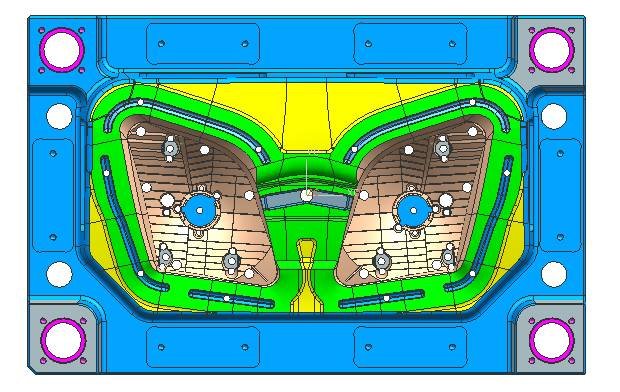
This plastic part is one of the most important exterior trimming parts of the vehicle, and it is a high-gloss part, and the surface needs vacuum electroplating. When designing the mould, first pay attention to the selection of mould materials. Due to poor material mobility of BMC, overflow chute shall be designed around the dynamic template cavity, and push rod shall be designed at the bottom of overflow chute to facilitate overflow ejection, as shown in Fig. 11. The BMC thermoset material is filled with fiberglass, and the mold needs high wear resistance, thermal redness and thermal fatigue resistance. Due to strict light distribution requirements of reflector, the core shall have good polishing performance. Therefore, Germany 2344ESR hot work tool steel with excellent hardenability is used as the fixed mould material, and the quenching hardness is 48~52HRC. The steel is remelted by vacuum electroslag, which improves the crystal uniformity of the steel and has excellent polishing effect. Fixed dies are often polished after hard chromium plating to reduce surface roughness, improve wear resistance and prevent rust. Dynamic die, dynamic die insert material adopts German 2344HT hot work tool steel, with hardening hardness of 48~52HRC.
The insertion angle of the opposite insertion part of the fixed and moving dies of the die shall be at least 7 degrees. In order to ensure the accurate positioning of the fixed and moving dies, the fixed and moving dies of the die shall be positioned with four corner rabbets and four sides of the circumference. Due to the precise positioning of the insertion part, the fixed and moving dies need to be closely matched during the FIT die. In order to make the die beautiful and matched, a 5-degree wear-resistant block is designed in the fixed die, so as to avoid the phenomenon that the fitter grinds the die with a grinding machine. At the same time, the wear-resistant block is designed to facilitate the fitter to match the mold and ensure the beauty of the mold.
The following points are also achieved in the design of the die:
1) The parting surface shall be smooth without sharp corner, thin steel, wireless or dot sealant; The surface sealing glue is constructed, and the surface preparation methods such as extension, sweeping and grid are used in the parting process. The parting surface is constructed according to the shape of the plastic part. The parting surface of the lamp mould has a very high requirement, and the surface that is constructed is not allowed to wrinkle. The constructed parting surface can effectively ensure the machining accuracy of CNC, without EDM corner cleaning, and the parting surface is not easy to run rough. High-speed machine is required for parting surface finishing knife of lamp mould, and the rotation speed of machine tool spindle shall be at least 20000 revolutions per minute.
2) For the fitting part between the insert and the moving die, the rabbet root is designed with appropriate process chamfer or avoidance position, which simplifies the processing process and reduces the processing time and improves the processing efficiency.
3) R angle shall be designed for all non-formed corners to prevent stress cracking. Process R angle shall not be less than R5. Larger process R angle shall be designed as far as possible according to the size of mould; Sharp edges on the die are easy to cause accidental injury to the operator. The edges not involved in forming or matching on the die shall be designed with chamfer C or R, and larger chamfer shall be designed as far as possible according to the size of the die.
4) Void avoidance of parting surface: the parting surface width of the mould is 40MM, and the fixed and moving moulds outside the parting surface shall be voided by 1MM, so as to effectively reduce the processing time. The avoidance of parting surface not only refers to the peripheral parting surface, but also includes a large area of parting surface. Special note: the width of the mould parting surface includes the exhaust slot. The pressure-bearing block shall be designed at the large-area void place to ensure the uniform stress of the die and avoid the die from running away for a long time. While the void is designed in the area where the die is punched, the exhaust hole shall be designed in the fixed die or the movable die to facilitate the exhaust of the compressed air when the fixed die and the movable die are combined.
5) The parting surface is constructed according to the shape of the plastic part, and the plastic part is optimized if necessary. For medium and large moulds, the bearing plate slot shall be opened as far as possible to facilitate CNC machining. The parting surface shall be designed based on the principle of simplified die processing and smoothness. The parting surface shall be free of thin steel and sharp corner and the insertion angle shall be reasonable.
6) The parting surface shall be smooth and flat. During UG parting, it is forbidden to have many small broken surfaces (easy to snap tools during CNC machining, with reduced machining accuracy). The parting surface shall be constructed by using the extension surface, grid surface and sweeping surface as far as possible, or the 10-20mm sealing surface shall be extended first, and then the stretching surface and transition surface shall be made. The sealing surface shall be designed according to the tonnage of the injection molding machine and the size of the mould.
7) All insertion angles of parting surface or insertion hole are designed to be above 7 degrees to improve the service life of mould.
Design of pouring system
The mold pouring system adopts “common runner+sector gate”. As the plastic parts are BMC materials with poor mobility, the flow passage shall be coarse and short when designing the flow passage. In order to reduce the excessive shear heat generated during the injection process and improve the injection speed, the molten BMC material is not allowed to solidify before filling the high-temperature mold cavity. Generally, a fan-shaped flow channel is set in the moving mold, and the gate thickness is 2.0-2.5mm.
Design of temperature control system
The headlamp reflector of automobile is one of the most important exterior trimming parts of automobile, and also one of the plastic parts with the highest appearance requirements. Therefore, the design of temperature control system has a great impact on the molding cycle of mould and the molding quality of product. Since the plastic parts are made of BMC materials, the injection molding process of BMC materials is completely different from the common thermoplastic injection molding process. The barrel of the injection molding machine needs to be cooled with ice water from a special chiller, while the core in the mold cavity needs to be electrically heated.
The arrangement of the heating pipe is similar to that of the waterway and the water well, which can be designed to be vertical or horizontal. The forming surface of the plastic part is 40-50mm away from the electric heating tube, and the distance between two electric heating tubes is 80-100mm. In order to improve the heating efficiency, a 8mm thick bakelite insulation board shall be designed on all sides of the fixed and moving die. Because the electric heating tube has no positive and negative poles, it can be connected in series, but each set of the thermostat socket shall not exceed 3.6KW. The temperature of each group of electric heating tubes is controlled by a set of thermocouples, which shall be in the center of the temperature field of the group of electric heating tubes, and the thermocouple head shall be in effective contact with the mould cavity, which is conducive to accurate temperature control. As shown in Figures 5 and 6.
The temperature control system of the fixed mold and the moving mold of this mold is: each hole of the fixed mold is designed with 2 vertical heating tubes, and the fixed mold is set with 4 horizontal heating tubes. Each hole of the dynamic mold is designed with 3 vertical heating tubes and 2 horizontal heating tubes. When arranging the heating pipe, pay attention to the trunking. The trunking corner shall be rounded to avoid damaging the line. Each mould shall be designed with a temperature probe, and the spacing of heating tubes shall be uniform. The heating tubes shall be ordered from the supplier. The hole of the heating tube shall be 1mm larger than the heating tube, and the depth shall be 1mm, because it will expand when heating.
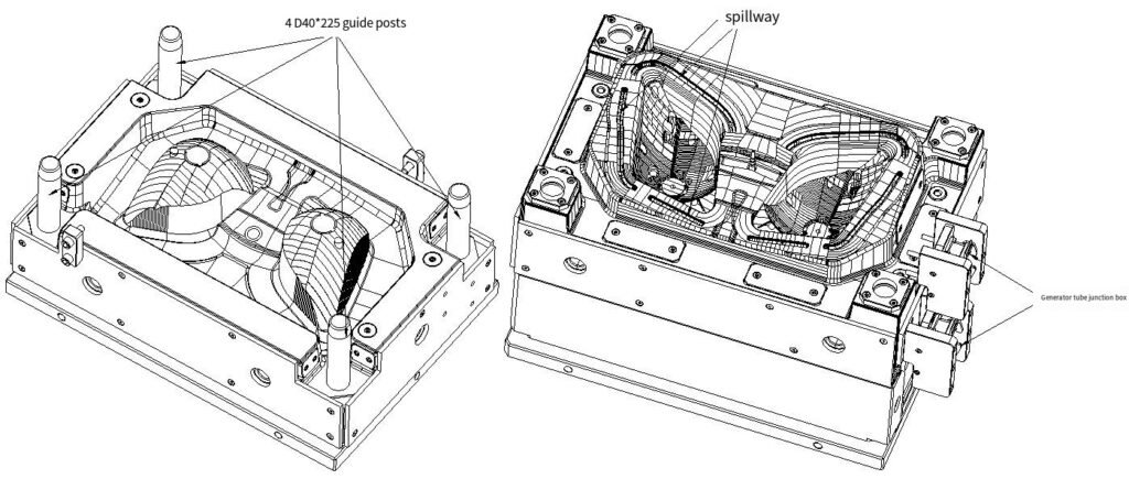
4.Design of guiding and positioning system
One D40 * 225 round guide post is designed on four corners of the die. The guide post shall be 10 times longer than the diameter) The guide post shall be installed at the fixed mold side. Since the plastic part is left at the moving mold side after the mold is opened, the removal of the plastic part will not be affected, and the plastic part shall be prevented from adhering to the oil stain on the guide post.
The guide post can also be used as the supporting foot when the formwork is turned over, so as to facilitate the FIT formwork, as shown in Figure 7. The length of the round guide post must ensure that the guide sleeve is inserted 20mm before the inclined guide post is inserted into the slider during die assembly, otherwise it will cause great trouble in die manufacturing and production, and even damage the die in serious cases. The design of die guiding system must pay attention to the design of three-level positioning, especially the automotive plastic parts with high requirements. Improper guiding and positioning design of the mold will cause the mold movement to be not smooth, the mold is easy to be damaged, the fixed and moving molds are displaced, the plastic parts have a segment difference and other problems, which are important systems for injection molding.
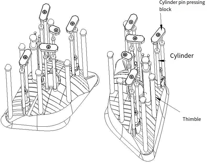
5.Design of demolding system
The ejection structure of the die is a ejector pin (push rod). After the die is opened in the fixed and moving die, the plastic part and the flow channel condensate are pushed out by the push rod. After the die is installed, the fixed plate of the push part is connected with the ejector pin of the injection molding machine by pulling reset 25. The ejector pin, reset rod and other push parts are pushed out and pulled back by the ejector pin of the injection molding machine. There is no need to add reset spring beside the 4 reset rods, but the reset block 26 shall be designed at the fixed template position contacting with the reset spring. The material is S50C and the surface is nitrided.
Attention shall be paid to the following points when designing the mould demolding system:
1) The guide post of push rod plate shall be arranged near the pushing elements with large pushing force (such as oil cylinder and reset rod).
2) Limit post shall be designed for all automobile injection molding dies, and the limit post shall be preferentially arranged in K O ABOVE OR NEAR HOLE.
3) The push rod shall be arranged at the stress position near R and the position with large wrapping force. For BMC thermoset materials, the design of push rod specification shall be large and the number of push rods shall be large to ensure the ejection balance. This is because the plastic parts of BMC are very hard, the clamping force to the mould is large, and the ejection force is also large.
4) The diameter of push rod shall be designed with the same size as far as possible, so as to avoid frequent replacement of drill bit and save processing time and cost.
5) All special-shaped surface push rods must be designed to stop rotation to avoid wrong assembly. The surface of the push rod is illuminated with mesh to avoid slipping of the push rod during ejection.
6) The needle return hole is designed with a void on one side (the void of small and medium-sized moulds is 0.5, and the void of large moulds is 1.0). The needle return end is designed with a process screw hole. In order to facilitate processing and clamping, when the diameter of return pin is greater than or equal to 20MM, a return block shall be designed on the opposite side of the return pin. The ejection hole of the injection molding machine shall not interfere with the garbage nail and support column.
6.Design of Molded Structural Parts
The die is guided and supported by 4 D40 * 225 guide posts, with good overall strength. During the injection process, the strength of the formwork will be affected to some extent by the injection pressure. Therefore, in addition to sufficient strength of the mould blank, some auxiliary structural parts shall be designed to strengthen the strength and service life of the mould.
Pay attention to the following points during design:
1) For the convenience of FIT die and processing, 4 process screws are designed between the ejector pin base plate and the code plate of the die. The specification of the process screw shall be one larger than that of the ejector pin plate screw. The word “process screw” is engraved beside the process screw, because the process screw is removed during die production. The purpose of this design is to facilitate the fitter to identify and prevent errors. Limit column shall be arranged above or near KO hole as far as possible. Garbage nails shall be arranged at the bottom of inclined top and straight top or near the top, with a spacing of about 150mm.
2) The pressure-bearing block on the parting surface of the mold sinks into the mold. The pressure-bearing block and precise positioning cannot be opened with oil groove. The pressure-bearing block groove shall be at least 15mm away from the edge of the mold frame.
3) Design of stop post: the mould mechanically ejected is designed above the top rod hole; The cylinder ejecting die is designed above or near the cylinder.
4) Design of support column: the distance between the support column and the square iron shall be kept at 25-30mm, and the distance between the support column and the support column shall be 80-120mm. The total area of the support column is 25% – 30% of the area of the push rod fixing plate. Support columns shall be designed in the adhesive feeding area and plastic projection area, and the support columns shall be designed as large as possible. Because of the concentration of injection pressure in these areas, the parting surface is prone to flash, so multiple design of support columns can reduce the generation of parting surface and flow path flash. Arrange the supporting heads at the hollowed position of the mould and the position with weak strength, such as the bottom of the slider and the bottom of the inner core.
5) The bottom of the return pin must be designed with a garbage nail (the garbage nail is designed on the base plate); If the ejection system consists of two plates, a fastening screw must be designed near the return pin to avoid deformation of the ejector pin plate.
7.Die working process
The melt enters the mould cavity through the nozzle of the injection molding machine and nozzle 12. After the melt is filled in the mould cavity, it is held in pressure, cooled and solidified to a sufficient rigidity. The injection molding machine pulls the movable mould fixing plate 10 of the mould, and the mould is opened from the parting surface PL I. When the mould is opened for 300mm, the oil cylinder of the injection molding machine pushes the fixed plate 8 of the pusher, and the fixed plate of the pusher pushes the push rod 28. Then, the oil cylinder of the injection molding machine continues to act. After being ejected for 70mm, the plastic part and the moving mould are separated. After the plastic part is removed by the manipulator, the oil cylinder of the injection molding machine pulls the pusher and the fixed plate to reset. Then, the injection molding machine pushes the moving mould to close, and the mould starts the next injection molding.
Mold strength and pipe position design of parting surface
The pipe position of the parting surface of the die is designed on the fixed and moving die, and the design form of combination of the four-corner rabbet and the four sides is adopted, so that the positioning is reliable and the die strength is good. In the design of auto dies, the insertion angle of fixed and moving dies shall be designed above 7 ° as far as possible, or above 5 ° if it is really impossible. Because the insertion angle is large, the service life of the mold will be greatly improved, and the phenomenon of the edge at the insertion of the mold will be greatly reduced. For the position with insertion angle below 3 degrees, 1 degree precise positioning and 0 degree precise positioning are difficult to ensure accurate positioning of fixed and moving dies, so the insertion angle shall be as large as possible. For large and medium-sized dies, it is generally designed above 7 degrees, so as to ensure the service life of dies.
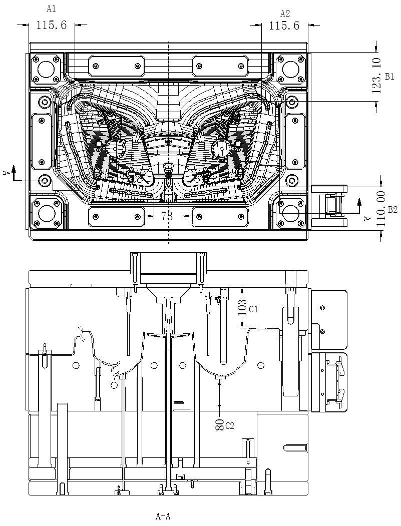
The main dimensions that affect the strength and rigidity of the mould include:
1) Dimensions A1, A2, B1 and B2 from cavity edge to die edge;
2) Distance C1 and C2 from the deepest part of the cavity to the bottom of the fixed and moving templates, see Figure 10.
In the design of automobile mould, the empirical determination method of dimension A and B is:
1) If there is no lateral core extracting mechanism, add 30~50mm sealant size from the outermost edge of the mould cavity (add 30mm for small mould within 5050, add 40mm for medium mould within 5050~1010 and add 50mm for large mould above 1010), and add 50~70mm void space to reduce the workload of mould matching. Vacancies are also areas where die strength is assured. Then add the dimension of the pressure bearing plate on the sub-section surface of the formwork, which is the dimension of A and B.
2) If there is a lateral core extracting mechanism, the dimensions A and B must be increased according to the core extracting distance. In principle, it must be ensured that the slider remains in the formwork after the core extracting is completed.
For plastic parts of different sizes and structures, the value of mould dimension C will be different. Dimension C must ensure that the steel thickness from the deepest part of the mould cavity to the bottom of the mould is more than 80mm. In the dynamic mould, since there is a void between two pieces of square iron, it is easy to deform after bearing the injection pressure, so the thickness of C1 shall be increased accordingly, generally more than 100mm.
Since the mould is one-out-of-two, the cavity II is bilaterally symmetrical, A1=A2=115.6mm, and the distance between the left reflector and the right reflector cavity is 73mm. As the die has no lateral core extracting mechanism, B1=123.1mm, B2=110mm. In terms of thickness, C1=103mm, C2=80mm. Plate B is relatively thin and shall be designed to be about 100mm as far as possible.
8.Mould exhaust system and discharge design
Ordinary thermoplastic molding is a physical change process, while the injection molding of thermoset plastic is a chemical reaction process. When a chemical reaction occurs, a large amount of volatile gases will be generated.
These gases have a great resistance to the injection molding, resulting in bubbles and lack of material on the surface of the plastic part. At the same time, the gas is compressed to produce high-temperature burned plastic parts. Therefore, the exhaust of the thermoset injection molding mold cavity is very important. For the general mold parting surface, the high-temperature seal ring shall be set at the bottom of the fixed and moving mold inserts. Vacuum pumping shall be adopted at the end of the material flow of the fixed mold cavity to overcome the molding defects and improve the injection speed. Insert is used for the moving die of the die, and the clearance between the insertion pin and the moving die is exhausted. Due to poor mobility of BMC, overflow chute shall be designed around the dynamic model cavity, and ejector pin shall be designed at the bottom of overflow chute to facilitate overflow ejection, as shown in Fig. 10.
9.Results and discussion
For automobile lamp reflector mould, the main design points include:
1) Special injection molding process equipment is required, and the injection molding machine specially producing BMC plastics shall be adopted, so the requirements for injection molding process equipment are very strict.
2) BMC material belongs to special hard plastic, heating system and parting surface design discharge system shall be designed in die design, and formed parts must be quenched to improve wear resistance and die life.
3) The reflector plastic part is a device to prevent the light from direct reflection, reflect the light and avoid the light from direct reflection on the vehicle lamp. The light distribution requirements are strict. Plastic parts are the most important appearance parts of automobiles. There are many patterns on the surface of plastic parts for decoration and beauty.
4) The ejection system of BMC material mould shall be balanced. The specification of push rod shall be designed as large as possible and the quantity shall be as much as possible. Otherwise, it will cause difficulties in demolding of plastic parts.
5) Because too small demolding inclination of high photoelectric plating parts will cause difficulty in demolding, the demolding inclination of the side wall of the reflector plastic parts shall be designed as large as possible, generally 5 ° – 10 °. Of course, the premise is that the function and shape of the plastic part cannot be affected.
6) Plastic parts shall not have sharp corners and sharp edges. All corners shall be designed as round corners, because the formed parts of the mould are prone to stress cracking after quenching.
7) Note that the left and right reflector lamp cap holes and the surface pattern of the plastic part are horizontally moved from left to right, and cannot be designed as mirror symmetry, because the bulb and the lamp cap are not left to right, and other features are mirror symmetry.